Optical drive sound producing device

A sound-generating device and light-driven technology, applied in the fields of optics and sound, can solve problems such as harmonic distortion and affecting sound fidelity

Inactive Publication Date: 2012-01-11
TIANJIN UNIV
View PDF5 Cites 0 Cited by
  • Summary
  • Abstract
  • Description
  • Claims
  • Application Information

AI Technical Summary

Problems solved by technology

[0005] 3. The nonlinear characteristics of electromagnetic and mechanical motion in the existing speakers cause the speakers to generate high-order harmonics, which easily cause harmonic distortion, thereby affecting the fidelity of sound production

Method used


Image

  • Optical drive sound producing device
  • Optical drive sound producing device
  • Optical drive sound producing device

Examples


Embodiment 1

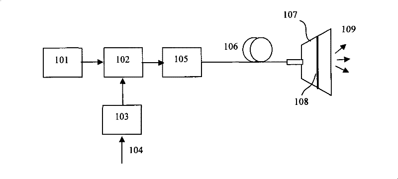
[0037] as attached figure 1 As shown, the light source 101 adopts the PIL106 semiconductor laser provided by Pilas, A.L.S.GmbH, Germany. The semiconductor laser can generate both continuous output and pulse output, and its output mode is set by its current control unit EIG1000D. The output wavelength of PIL106 semiconductor laser is 1060nm, and the continuous output power is greater than 400mW. The optical intensity modulator 102 adopts a high-speed variable optical fiber attenuator (VOA) μVOA302 provided by BATI of the United States. The VOA uses electro-optic ceramics as the switch material, the dynamic response time is 1μS, and the insertion loss to the wavelength of 1060nm is less than 0.6dB. The dynamic attenuation range is 25dB, and the reflection loss is greater than 55dB. Electro-optic ceramics have a strong Kerr effect, the electro-optic coefficient is 2 orders of magnitude larger than that of niobium lithium oxide, and the half-wave voltage is much lower than that ...

Embodiment 2

[0041] as attached figure 1 As shown, the light source 101 adopts PIL106 semiconductor laser, and its output mode is set as pulse output by its current control unit EIG1000D, the pulse width is selected as 40 ps, ​​and the repetition frequency is set as 1 MHz. The optical intensity modulator 102 adopts the high-speed variable optical fiber attenuator μVOA302 provided by BATI in the United States, and the optical fiber amplifier 105 is a high peak power pulse amplifier. The connection mode of various devices is similar to that of Embodiment 1. The difference is that the pulse energy of the sequence light pulse is modulated by the light intensity of the audio signal 104, as shown in the attached Figure 4 shown. The sound-emitting film 108 is a gold foil with a thickness on the order of submicron. When a light pulse is incident on the surface of the gold foil, part of the light is reflected and part is absorbed. The absorbed light energy is converted into heat energy, formin...

Embodiment 3

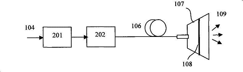
[0043] as attached figure 2 As shown, the semiconductor light emitting device 202 adopts a 6397 series semiconductor laser with pigtail output from the American JDSU company. The semiconductor laser is multi-mode continuous output, its continuous output wavelength is 915nm, the maximum output is 6.5W, the output pigtail fiber core diameter is 105 microns, and the driving current is greater than 6A. The current driving source 201 adopts THORLABSLDC340 semiconductor laser current driving source, and the audio signal 104 is connected to the modulation input (MOD IN) end of the LDC340. The output of the semiconductor laser whose light intensity is modulated is connected to the shell of the sounding body 107 through the transmission fiber 106 , and is incident on the sounding film 108 . The optical signal whose intensity is modulated by the audio signal 104 is absorbed by the sound-emitting film 108 and converted into heat energy, so that the temperature of the sound-emitting fil...


PUM


Abstract

The invention relates to an optical drive sound producing device. The sound producing device which comprises an optical source, an optical modulator, an optical amplifier, a transmission optical fiber and a sound producing film, wherein the strength of output light generated by the optical source is modulated by an audio signal through the optical modulator, and the output light is amplified by the optical amplifier and projected on the sound producing film; the sound producing film absorbs incident light to cause temperature change and lead an air layer approaching the sound producing film to generate thermal expansion changed along light strength so as to cause air medium density change and produce sound. The sound producing process generated in an optical drive way is a linear process,cause no harmonic distortion on a principle and has high sound producing fidelity. Compared with the prior electric sound producing device, the sound producing device does not need to use a magnet and a sound coil, thereby having no response to the external magnetic field and normally working in an environment with a strong electromagnetic field; and the sound producing device does not need to use metal or other conductor materials, and the energy needed by sound production can be transmitted in a space or by an optical fiber.

Description

【Technical field】: [0001] The invention relates to a sounding device, in particular to a sounding device driven by an optical signal, and belongs to the technical fields of optics and sounding. 【Background technique】: [0002] Existing sound generating devices and devices, such as loudspeakers (also known as horns) and earphones, are sound generating devices that convert electrical energy into sound energy. Although there are many types of existing loudspeakers and their working methods are not the same, the principle of sound generation is to generate mechanical vibration through certain vibrating parts, push the surrounding air, and cause the air medium to fluctuate so as to realize electrical energy to mechanical energy and then to sound energy. conversion. Loudspeakers can be divided into dynamic loudspeakers, electrostatic loudspeakers, and flat-panel loudspeakers. Among them, the most widely used is the dynamic speaker. Common electrodynamic loudspeakers are general...

Claims


Application Information

Patent Timeline
Patent Type & Authority Patents(China)
IPC IPC(8): G10K9/00
Inventor 李恩邦
Owner TIANJIN UNIV
Why Eureka
Try Eureka