Amplifier circuit

a technology of amplifier circuit and amplifier, which is applied in the direction of amplifier, amplifier, amplifier with semiconductor device/discharge tube, etc., can solve problems such as harmonic distortion, and achieve the effects of reducing harmonic distortion, suppressing spike generation, and eliminating the influence of amplifier slew ra

Inactive Publication Date: 2009-03-24
GAKKOUHOUJIN CHIKOUJIGAKUEN +1
View PDF1 Cites 0 Cited by
  • Summary
  • Abstract
  • Description
  • Claims
  • Application Information

AI Technical Summary

Benefits of technology

[0029]The present invention has been made in view of the above-mentioned circumstances, and therefore, it is an object of the present invention to provide a chopper amplifier circuit capable of obtaining an output signal obtained from an input signal alone, the output signal having no harmonic distortion as compared with a conventional example, by eliminating an influence of a slew rate of an amplifier and suppressing spike generation.
[0036]Therefore, according to the chopper amplifier circuit of the present invention, the amplified signal is read out from the hold circuit at a timing shifted by a half cycle from a timing at which the amplified signal from the amplifier is sampled, to thereby output the amplified signal in a state where the output is completely stable. Accordingly, it is possible to suppress spike generation by eliminating the influence of the slew rate of the amplifier when synthesizing the amplified signal.
[0037]As described above, the chopper amplifier circuit of the present invention is provided with the sample hold circuit connected in tandem at a subsequent stage of the amplifier, so the amplified signal outputted from the amplifier is temporarily held to eliminate the influence of the slew rate of the amplifier so as to prevent spike component generation, thereby producing an effect of reducing a harmonic distortion included in the output signal which has been outputted through the low-pass filter, as compared with the conventional example.

Problems solved by technology

However, the chopper amplifier circuit described in Non-Patent Document 1 has a drawback in that it is impossible to completely remove spike components included in the output signal through the low-pass filter 13, leading to a harmonic distortion.

Method used


Image

  • Amplifier circuit
  • Amplifier circuit
  • Amplifier circuit

Examples


Embodiment Construction

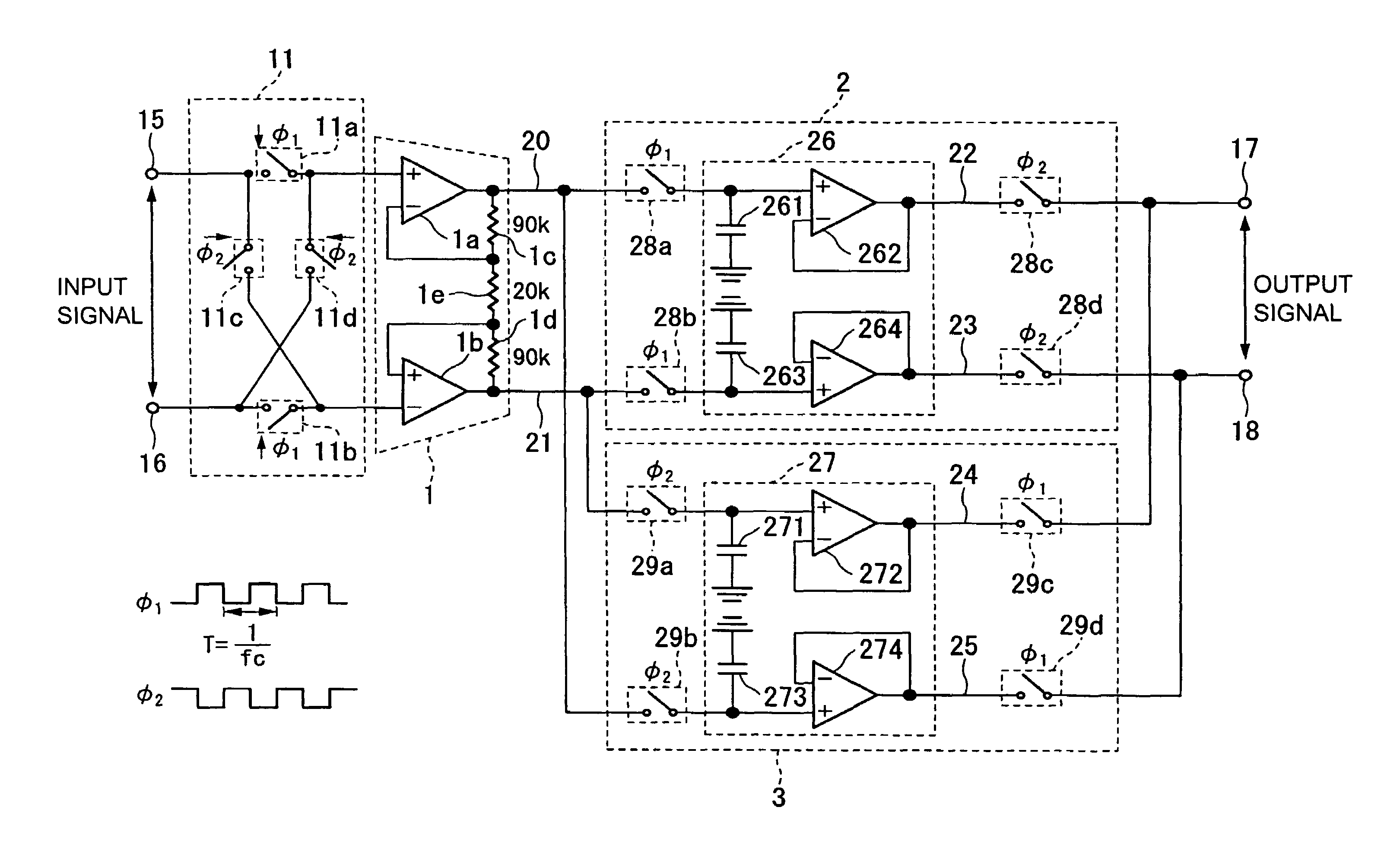
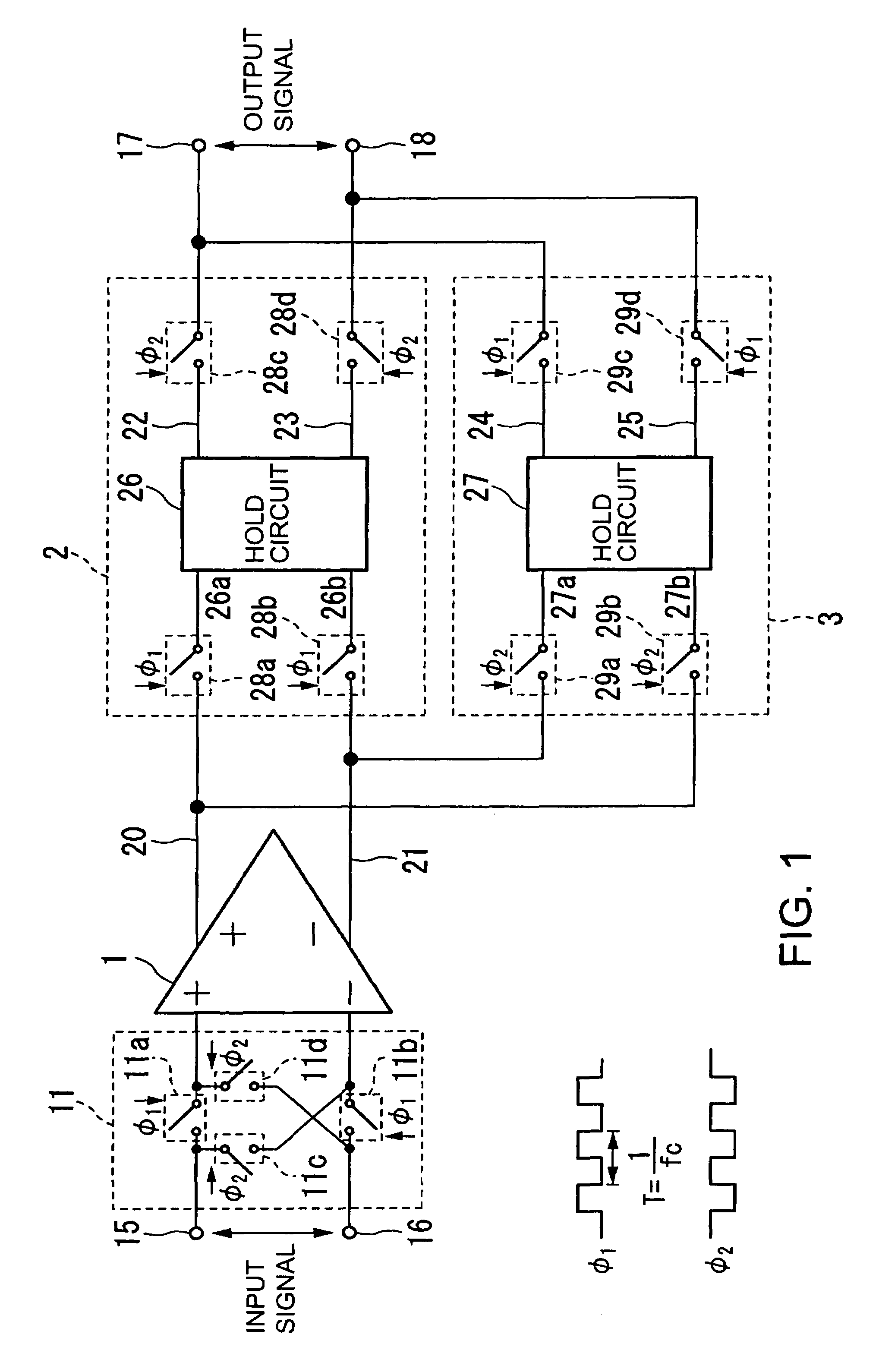
[0055]Hereinafter, a chopper amplifier circuit according to an embodiment of the present invention is explained with reference to the accompanying drawings. FIG. 1 is a block diagram showing a configuration example of the chopper amplifier circuit according to this embodiment.

[0056]In the drawing, the components similar to those of a conventional example of FIG. 9A are denoted by the same reference symbols and an explanation thereof is omitted. That is, a chopper circuit 11 and an amplifier 1 are similar to those in the conventional example of FIG. 9A. The circuit of FIG. 1 is different from the conventional example in that the circuit includes sample hold circuits 2 and 3 connected in parallel, in place of the chopper circuit 12 in the conventional example, at the subsequent stage of the amplifier 1.

[0057]The circuit of this embodiment operates similarly to the conventional example, so a brief explanation is given on a configuration of the chopper circuit 11.

[0058]The chopper circu...


PUM


Abstract

Provided is a chopper amplifier circuit capable of eliminating an influence of a slew rate of an amplifier and suppressing spike generation to thereby obtain an output signal having little harmonic distortion. The chopper amplifier circuit according to the present invention includes: a first chopper circuit for chopping an input signal by a first pulse and a second pulse shifted from each other in phase by a half cycle, switching a relation of connection between an input terminal pair and an output terminal pair at a timing of the chopping, and outputting the input signal as a modulated signal; an amplifier for amplifying the modulated signal and outputting the modulated signal thus amplified as an amplified signal; a first sample hold circuit for holding the amplified signal at the first pulse and outputting the amplified signal at the second pulse; and a second sample hold circuit for holding the amplified signal at the second pulse and outputting the amplified signal at the first pulse.

Description

[0001]This application claims priority under 35 U.S.C. §119 to Japanese Patent Application No. JP2006-029138 filed Feb. 7, 2006, the entire content of which is hereby incorporated by reference.BACKGROUND OF THE INVENTION[0002]1. Field of the Invention[0003]The present invention relates to a chopper amplifier circuit capable of reducing a DC offset and noise in an amplifier, and more particularly, to a chopper amplifier circuit capable of reducing an influence of spike noise.[0004]2. Description of the Related Arts[0005]A chopper amplifier circuit has widely been used as a low-noise low-drift DC amplifier.[0006]A conventional chopper amplifier includes, as shown in FIG. 9A, an amplifier 1 and chopper circuits 11 and 12 provided at a preceding stage and a subsequent stage of the amplifier 1, respectively, so as to attain low-noise amplification.[0007]The chopper circuit 11 employs four switching means, which are turned on and off in accordance with pulses φ1 and φ2 shown in FIG. 9B. T...

Claims


Application Information

Patent Timeline
Patent Type & Authority Patents(United States)
IPC IPC(8): H03F1/02
CPCH03F1/3211H03F3/387H03F3/45475H03F3/45986H03F3/45995H03F2203/45138H03F2203/45212H03F2203/45614H03F2203/45616H03F2203/45681H03F2203/45726H03F1/26
Inventor YOSHIZAWA, HIROKAZUANZAI, RYOICHIUCHIDA, TOSHIYUKITAKEDA, AKIRAARIYAMA, MINORUIGARASHI, ATSUSHI
Owner GAKKOUHOUJIN CHIKOUJIGAKUEN
Why Eureka
Try Eureka