
Fixing device and image forming device including the fixing device

A technique for fixing rollers and pressure rollers, which is applied to electrical recording technology using charge patterns, equipment and instruments for electrical recording technology using charge patterns, etc., can solve problems such as poor conveyance of recording sheets, and achieve the effect of suppressing poor conveyance

Active Publication Date: 2011-12-21
SHARP KK
View PDF2 Cites 0 Cited by
  • Summary
  • Abstract
  • Description
  • Claims
  • Application Information

AI Technical Summary

Problems solved by technology

[0009] In addition, the pressure contact mechanism for pressing the pressure roller toward the fixing roller, the pressure release mechanism for releasing the pressure contact between the pressure roller and the fixing roller by the pressure contact mechanism, and the pressure contact mechanism for pressing the fixing roller from the outside are provided. In the case of a fixing device with an external pressing mechanism, if the external pressing mechanism presses the fixing roller from the side opposite to the pressure roller and allows the movement of the fixing roller to the side of the pressure roller, the following problems may occur situation
[0010] That is, since the external pressing mechanism presses the fixing roller from the side opposite to the pressure roller, and on the other hand allows the movement of the fixing roller to the side of the pressure roller, the pressure roller to the fixing roller performed by the pressure release mechanism When the crimping is released, the fixing roller will move to the pressure roller side under the pushing force of the external pushing mechanism, and the crimping pressure between the fixing roller and the pressure roller that should be properly released becomes larger than it should be. The release pressure is strong, which may cause poor conveyance of recording sheets such as envelopes.

Method used


Image

  • Fixing device and image forming device including the fixing device
  • Fixing device and image forming device including the fixing device
  • Fixing device and image forming device including the fixing device

Examples


Embodiment Construction

[0034] Hereinafter, an embodiment of the present invention will be described with reference to the drawings. In addition, the following embodiment is an example which actualized this invention, and does not limit the technical scope of this invention.

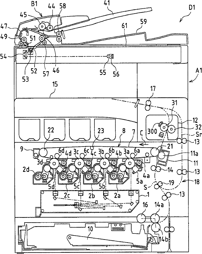
[0035] figure 1 It is a side view schematically showing an image forming apparatus D1 to which an embodiment of the fixing device of the present invention is applied. The image forming apparatus D1 includes a document reading device B1 for reading an image of a document, and forms the image of the document read by the document reading device B1 or an image received from the outside in color or monochrome on a recording sheet such as paper. on the device body A1.

[0036]In the document reading device B1, when a document is set on the document setting tray 41, the pickup roller 44 is pressed against the surface of the document to rotate, the document is pulled out from the tray 41, and the document passes through the separator...


PUM


Abstract

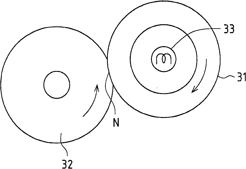
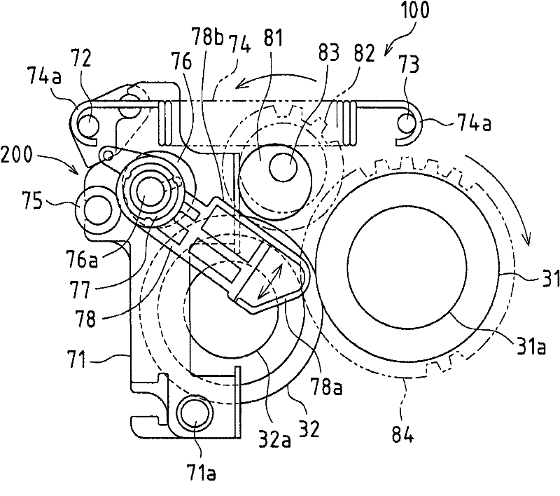
A fixing device (12) according to an embodiment of the present invention includes a fixing roller (31), a pressure roller (32), and a pressing device (100) for pressing the pressure roller (32) toward the fixing roller (31). , the pressure release device (200) that releases the pressure roller (32) from the pressure roller (32) to the fixing roller (31) by the pressure contact device (100), and presses the fixing roller (32) from the outside An external heating device (300) for the roller (31), and a limiting member (400) for limiting the pushing amount of the external heating device (300) to the fixing roller (31).

Description

[0001] This application is based on claim priority of Japanese Patent Application No. 2008-212031 filed in Japan on August 20, 2008. By mentioning here, the entire contents of which are incorporated into this application. technical field [0002] The present invention relates to a fixing device applicable to image forming devices such as copiers, facsimile machines, and printers, and an image forming device including the fixing device. Background technique [0003] In such an image forming apparatus, for example, in the case of an electrophotographic method, an electrostatic latent image is formed on the surface of an image carrier such as a photoreceptor drum, and the electrostatic latent image on the surface of the image carrier is developed by a developer. A toner image is formed on the surface of the carrier, the toner image is transferred from the image carrier to a recording sheet, and the recording sheet is heated and pressurized to fix the toner image on the recordin...

Claims


Application Information

Patent Timeline
Patent Type & Authority Patents(China)
IPC IPC(8): G03G15/20
CPCG03G15/2089G03G15/2067G03G2215/20G03G15/2032G03G15/206
Inventor 中村博一浪崎广介山中孝师塚本公秀
Owner SHARP KK
Learn More