
Paper feed roll

A technology of paper feed rollers and convex parts, which is applied in the field of paper feed rollers and can solve problems such as poor paper conveyance

Active Publication Date: 2020-10-30
SUMITOMO RIKO CO LTD
View PDF11 Cites 0 Cited by
  • Summary
  • Abstract
  • Description
  • Claims
  • Application Information

AI Technical Summary

Problems solved by technology

As a result, paper feeding failures sometimes occur

Method used


Image

  • Paper feed roll
  • Paper feed roll
  • Paper feed roll

Examples


Embodiment 1~17、 comparative example 1~4

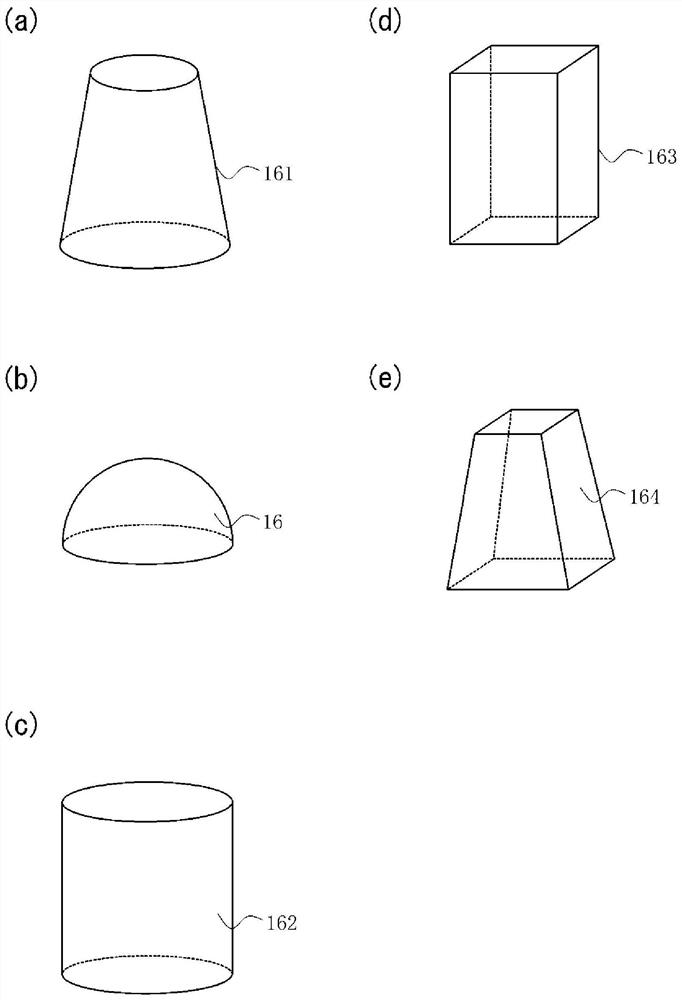
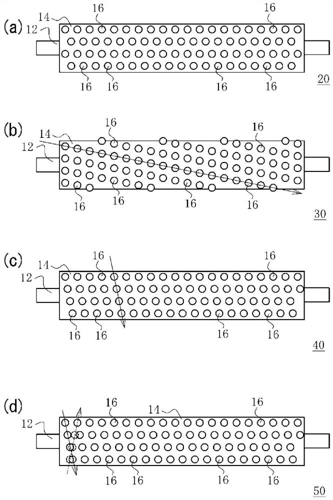
[0053] An elastic body layer (thickness: 3 mm) of a polyurethane rubber composition was formed on the outer periphery of a core material (φ6, made of SUS304) using a cylindrical molding die having a plurality of predetermined recesses on the inner peripheral surface. Thus, a paper feed roller having a predetermined plurality of protrusions on the peripheral surface of the elastic layer is obtained. Tables 2 to 4 show the shape of the protrusions, the arrangement of the protrusions, and the height of the protrusions. Table 1 below shows the correspondence relationship between the shape of the convex part and the figure number, and the relationship between the arrangement of the convex part and the figure number. Irregular protrusions were formed using a cylindrical molding die in which electrical discharge machining was performed on the inner peripheral surface. In addition, the corrugated protrusion shape was formed using a cylindrical molding die in which the inner periphera...


PUM


Abstract

Provided is a paper feed roll such that conveyance failures of paper are suppressed over a long period of time. This paper feed roll 10 comprises a shaft body 12 and an elastic body layer 14 formed onthe outer periphery of the shaft body 12. A plurality of protrusions 16 that form surface unevenness are formed on the peripheral surface of the elastic layer 14. When a glass plate is pressed against the peripheral surface of the paper feed roll 10 with a load of 0.5 to 2.3 N per cm length in the axial direction, the entire area of the portion in contact with the glass surface is 1.0 to 15% of the nip area with the glass surface.

Description

technical field [0001] The present invention relates to a paper feed roller suitable for use in electrophotographic equipment such as copiers, printers, and facsimiles using electrophotography. Background technique [0002] The paper feed roller is formed in a cylindrical shape, for example, from an elastic material such as cross-linked rubber, and its peripheral surface serves as a contact surface with the paper. Paper dust from paper may adhere to the surrounding surface of the paper feed roller. In addition, paper dust may accumulate on the peripheral surface of the paper feed roller during repeated contact with the paper. When paper dust accumulates, the contact area of ​​the peripheral surface with respect to the paper decreases, and the friction coefficient of the contact surface with respect to the paper decreases. As a result, poor conveyance of paper may occur. [0003] In order to suppress poor conveyance of paper, there is known a paper feed roller in which irr...

Claims


Application Information

Patent Timeline
Patent Type & Authority Applications(China)
IPC IPC(8): B65H5/06
CPCB65H5/06B65H2404/1118B65H2404/1141B65H2601/255B65H5/068B65H2511/135
Inventor 山口和志
Owner SUMITOMO RIKO CO LTD
Learn More