Diesel engine system with exhaust gas recirculation

a diesel engine and exhaust gas technology, applied in the direction of electrical control, process and machine control, instruments, etc., can solve the problems of reduced external air supply to the diesel engine, increased load of diesel engine, and increased smoke production, so as to prevent the production of smoke

Active Publication Date: 2008-08-28
MITSUBISHI HEAVY IND ENGINE & TURBOCHARGER LTD
View PDF12 Cites 27 Cited by
  • Summary
  • Abstract
  • Description
  • Claims
  • Application Information

AI Technical Summary

Benefits of technology

[0013]An object of the present invention is to suppress the production of the smoke during the increase in the load of the engine without inhibiting the reduction of the nitrogen oxide.
[0021]According to the above configuration, since the opening of the throttle valve is held constant for the predetermined holding time, an action is not inhibited in which the increase in the load of the diesel engine induces the increase in the flow rate of the intake air. Therefore, in the diesel engine system, the necessary flow rate of the intake air is secured and the production of smoke is prevented during the increase in the load of the diesel engine.

Problems solved by technology

Such control has one problem that much smoke is produced during the increase in the load of the diesel engine.
However, such control has an adverse effect that the necessary flow rate of the intake air is not secured during the increase in the load of the diesel engine.
However, the opening of the EGR valve is made to increase or the opening of the throttle valve is made to decrease in order to reduce the nitrogen oxide, the external air supplied to the diesel engine is reduced, and thus the necessary flow rate of the intake air is not secured.
In such case, incomplete combustion occurs in a combustion chamber of the diesel engine, and the smoke is produced.
However, the action to induce the increase in the flow rate of the intake air is not effective during the increase in the load.
Therefore, during the increase in the load, the problem is critical that when the opening of the EGR valve is made to increase or when the opening of the throttle valve is made to decrease, the necessary flow rate of the intake air is not secured and the smoke is produced.

Method used


Image

  • Diesel engine system with exhaust gas recirculation
  • Diesel engine system with exhaust gas recirculation
  • Diesel engine system with exhaust gas recirculation

Examples


Embodiment Construction

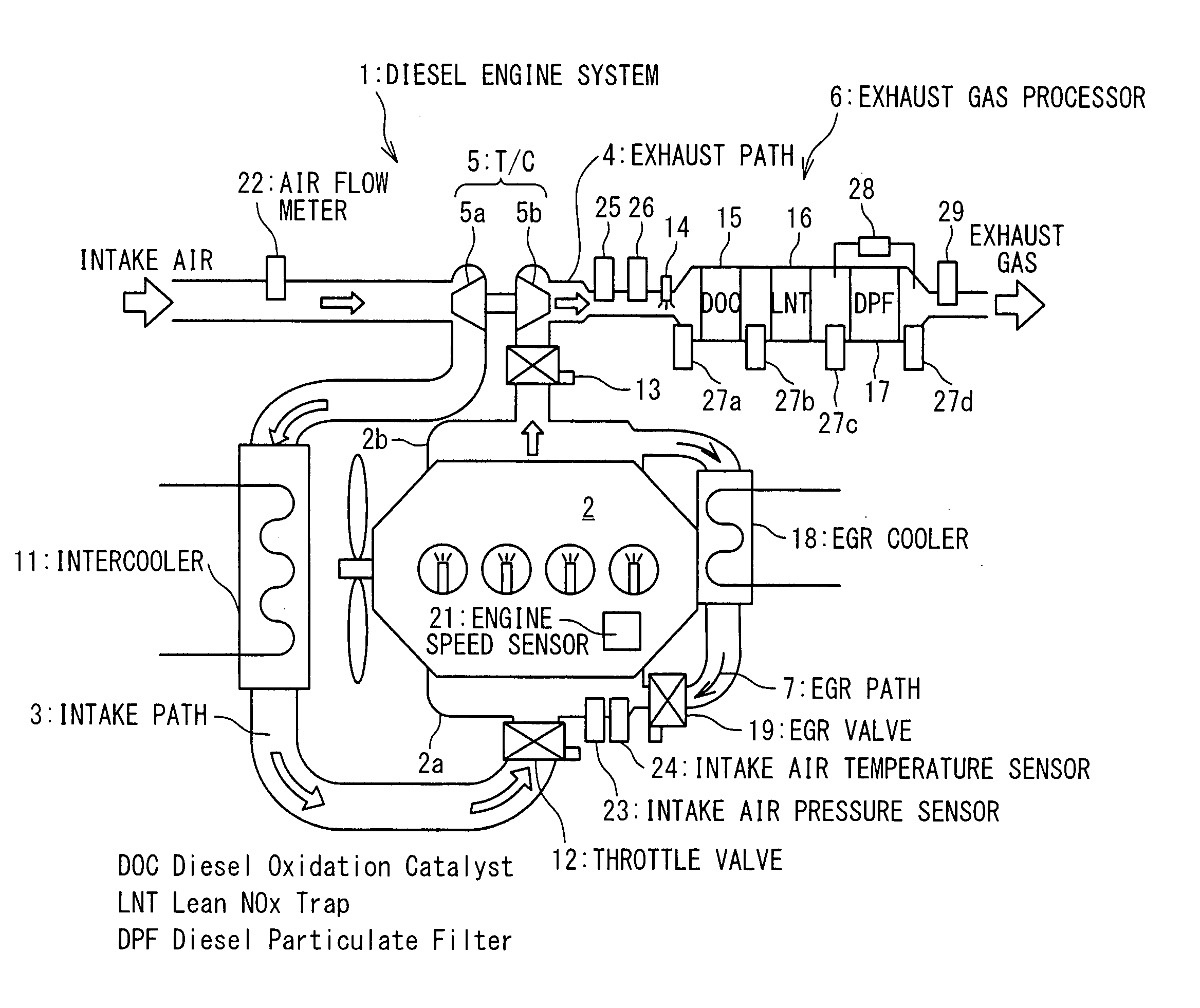
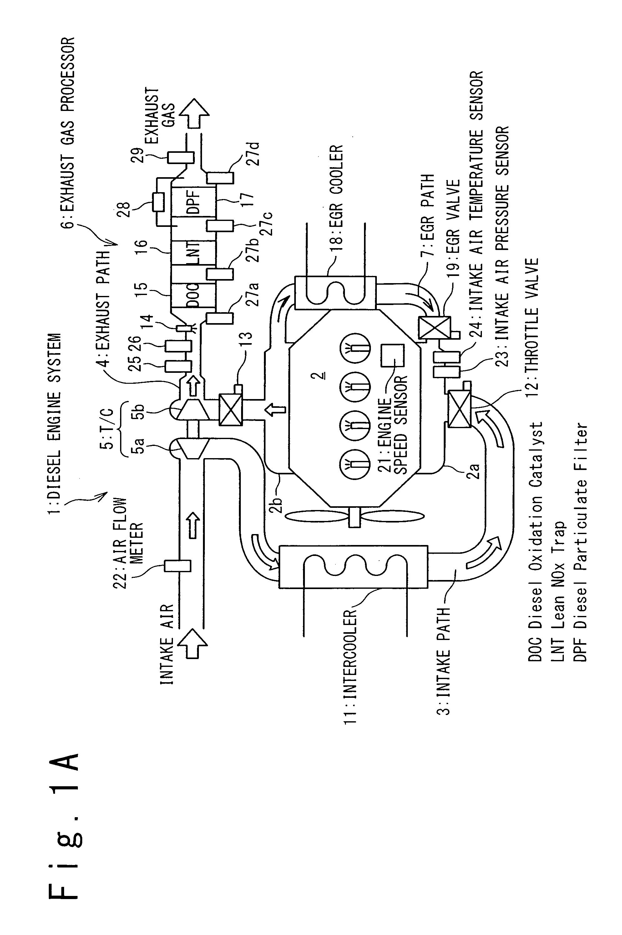
[0037]FIG. 1A shows a configuration of a diesel engine system 1 according to an embodiment of the present invention. The diesel engine system 1 includes a diesel engine 2, an intake path 3, an exhaust path 4, a turbo charger 5, an exhaust gas processor 6 and an EGR path 7. The intake path 3 is connected to an intake port 2a of the diesel engine 2, and the exhaust path 4 is connected to an exhaust port 2b of the diesel engine 2. The turbo charger 5 is driven by exhaust gas exhausted to the exhaust path 4 from the diesel engine 2 and compresses intake air. The exhaust gas processor 6 removes pollutant, such as NOx and PM, from the exhaust gas. The EGR path 7 is provided to connect the exhaust port 2b and the intake port 2a.

[0038]The intake path 3 is provided with a compressor wheel 5a of the turbo charger 5, an intercooler 11 and a throttle valve 12. The intake air compressed by the turbo charger 5 is cooled by the intercooler 11 and then supplied through the throttle valve 12 to the...


PUM


Abstract

A diesel engine system includes a diesel engine, a throttle valve, an EGR (Exhaust Gas Recirculation) path, an EGR valve and a controller. The throttle valve controls a flow rate of intake air to the diesel engine. Exhaust gas is recirculated along the EGR path from an exhaust port to an intake port of the diesel engine. The EGR valve controls a flow rate of the exhaust gas. The controller controls the throttle valve and the EGR valve such that an opening of the throttle valve decreases and an opening of the EGR valve increases when a load of the diesel engine increases. The controller controls the EGR valve such that the opening of the EGR valve increases after the opening of the EGR valve is held constant for a first predetermined holding time.

Description

BACKGROUND OF THE INVENTION[0001]1. Field of the Invention[0002]The present invention relates to a diesel engine system, and more particularly relates to reducing pollutant such as NOx (nitrogen oxide) and PM (Particulate Matter) in exhaust gas from a diesel engine. This Patent application is based on Japanese Patent application No. 2007-050719. The disclosure thereof is incorporated herein by reference.[0003]2. Description of the Related Art[0004]Exhaust gas recirculation (EGR) in which exhaust gas from a diesel engine is partially recirculated to an intake pipe is known as one of methods used to reduce nitrogen oxide in the exhaust gas. The exhaust gas includes no oxygen or oxygen of low concentration. Thus, when the exhaust gas is recirculated to the intake pipe, combustion is carried out in a state of low oxygen concentration. For this reason, a combustion temperature is decreased, thereby suppressing the production of NOx. The exhaust gas recirculation is disclosed in, for exam...

Claims


Application Information

Patent Timeline
Patent Type & Authority Applications(United States)
IPC IPC(8): F02D45/00
CPCF02B3/06Y02T10/47F02D41/0052F02D41/0065F02D41/1401F02D2041/0017F02D2041/0022F02D2041/1409F02D2041/141F02M25/0707F02M25/0713F02M25/0727F02M25/078F02M2025/0761F02M2025/0762F02B29/0406F02M26/05F02M26/10F02M26/23F02M26/60F02M2026/003F02M2026/004Y02T10/40F02D21/08
Inventor IDE, KAZUNARIENDO, HIROYUKISATO, SHINICHIOKAJIMA, AKIHIDE
Owner MITSUBISHI HEAVY IND ENGINE & TURBOCHARGER LTD
Why Eureka
Try Eureka