Exhaust purification device for internal combustion engine

a technology of exhaust purification device and internal combustion engine, which is applied in the direction of electrical control, separation process, instruments, etc., to achieve the effect of reducing catalyst and more accurate obtainmen

Inactive Publication Date: 2010-09-14
DENSO CORP
View PDF12 Cites 5 Cited by
  • Summary
  • Abstract
  • Description
  • Claims
  • Application Information

AI Technical Summary

Benefits of technology

[0010]It is an object of the present invention to provide an exhaust purification device of an internal combustion engine capable of achieving both of inhibition of deterioration of fuel consumption due to regeneration of a diesel particulate filter and inhibition of torque shock accompanying misfire during rich combustion for NOx reduction.
[0012]Thus, when an ECU determines that the cetane number of the fuel in use is low or the present location point is at the high altitude, the ECU switches a switching map of a NOx reduction method based on an operation area or rewrites map values so that an area for lengthening the fuel injection period or for performing the subsidiary injection immediately after the fuel injection (i.e., an area for performing the rich combustion) moves to the high rotation speed side or the high load side. Thus, the rich combustion, which tends to cause a misfire in a low rotation speed and low load state, is not performed when the low-cetane fuel is used or when the exhaust purification device is at the high altitude. Accordingly, the misfire and eventual torque shock can be inhibited. When the low-cetane fuel is used or when the exhaust purification device is at the high altitude, the ignition delay extends and therefore mixing of the air and the fuel is promoted. Therefore, the generation of the smoke is suppressed. In such the case, by performing the rich combustion also in a state of relatively high rotation speed and relatively high load, a high NOx purification efficiency and suitable fuel consumption can be attained.
[0014]Thus, the time from the fuel injection to the ignition is used as an index for estimating the cetane number. Timing for injecting the fuel can be controlled by the engine control unit (ECU) as a control section. Therefore, it is easy to measure the time after the fuel injection to the fuel ignition. The ignition time may be measured by providing a pressure sensor in a cylinder and by measuring timing when the pressure abruptly rises. Thus, the cetane number of the fuel can be determined more correctly.
[0016]Thus, a structure providing an intake pressure sensor on an intake side of the engine can correctly estimate whether the present point is at the high altitude. Accordingly, selection between the rich combustion device and the reducing agent addition device or selection between the rich combustion device and the post-injection device can be performed more appropriately. As a result, deterioration of the fuel consumption due to the regeneration of the DPF can be inhibited and torque shock accompanying the misfire during the rich combustion for the NOx reduction can be inhibited.
[0020]When the smoke passes through the filter section, part of the smoke is deposited in the filter as the particulate matters. Therefore, the measurement of the change in the particulate matter deposition quantity in the filter enables more accurate grasp of excessive discharge of the smoke. Accordingly, an efficient NOx reduction method can be selected.
[0022]When the particulate matters are deposited in the filter section, the exhaust gas is not discharged from the inlet to the outlet smoothly, so the difference arises between the air pressures at the inlet and the outlet of the filter section. Therefore, the measurement of the difference in the air pressure across the filter section with the differential pressure sensor enables more accurate obtainment of the quantity of the particulate matters deposited in the filter section. The exhaust purification device of the internal combustion engine having the configuration according to the aspect of the present invention can correctly calculate the quantity of particulate matters deposited in the filter section. As a result, the predetermined engine rotation speed and the predetermined load for switching between the rich combustion device and the reducing agent addition device or between the rich combustion device and the post-injection device as the devices for reducing the catalyst can be set more appropriately.

Problems solved by technology

Thus, the rich combustion, which tends to cause a misfire in a low rotation speed and low load state, is not performed when the low-cetane fuel is used or when the exhaust purification device is at the high altitude.

Method used


Image

  • Exhaust purification device for internal combustion engine
  • Exhaust purification device for internal combustion engine
  • Exhaust purification device for internal combustion engine

Examples


first embodiment

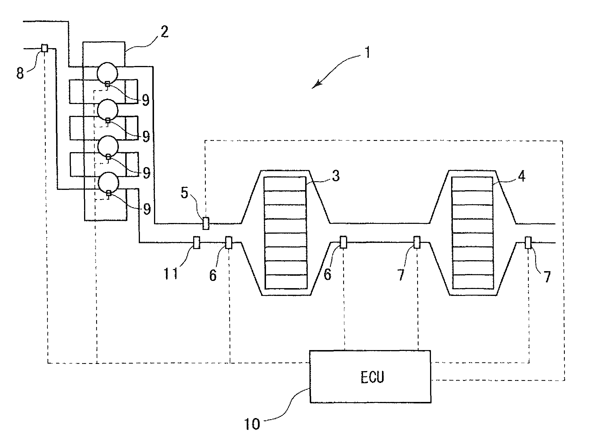
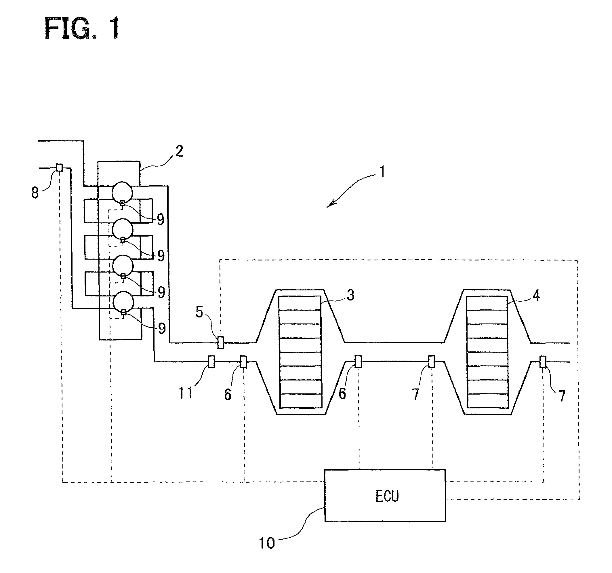
[0031]FIG. 1 is a system diagram showing an exhaust purification device of an internal combustion engine 1 according to the present invention. A diesel engine 2 shown in FIG. 1 serves as a motor. A diesel particulate filter 3 (DPF) as a filter section for collecting particulate matters contained in exhaust gas of the diesel engine 2 is arranged in a passage on an exhaust side of the diesel engine 2. Further, a Lean NOx trap 4 (hereinafter, referred to as LNT) as a catalyst of a NOx occlusion reduction type for removing nitrogen oxides (NOx) contained in the exhaust gas is arranged downstream of the DPF 3. The NOx occlusion reduction type catalyst occludes the NOx when an oxygen concentration of the exhaust gas is high and discharges the NOx when the oxygen concentration of the exhaust gas is low. The NOx performs an oxidation-reduction reaction with HC or CO contained in the exhaust gas when discharged and is oxidized or reduced to CO2, H2O and N2. The NOx in the exhaust gas is remo...

second embodiment

[0057]FIG. 5 is a flowchart showing an example of switching processing of the NOx reduction method according to the present invention. First, the ECU 10 measures the discharge quantity PMe of the smoke with the smoke sensor 11 and receives the measurement value in S200.

[0058]Then, the ECU 10 determines whether the measured discharge quantity PMe of the smoke is equal to or greater than the first predetermined value α in S210. When the discharge quantity PMe of the smoke is equal to or greater than the first predetermined value α (S210: YES), the ECU 10 determines that a large quantity of the smoke is generated and switches the switching map of the NOx reduction method or rewrites the map values so that the area for performing the rich combustion changes toward the low rotation and low load area side in S220. Then, the switching processing of the NOx reduction device is ended.

[0059]When the discharge quantity PMe of the smoke is less than the first predetermined value α (S210: NO), t...

third embodiment

[0061]FIG. 6 is a flowchart showing an example of switching processing of the NOx reduction method according to the present invention. First, the ECU 10 measures the differential pressure ΔP between the inlet and the outlet of the DPF 3 with the differential pressure sensors 6 and receives the measurement value ΔP in S300. Then, the ECU 10 calculates the particulate matter deposition quantity PMf from the measurement value ΔP in S310.

[0062]Then, the ECU 10 calculates an increase degree ΔPMf of the particulate matter deposition quantity PMf in S320. The increase degree ΔPMf of the particulate matter deposition quantity PMf is calculated from the particulate matter deposition quantity PMf and a travel distance. The increase degree ΔPMf may be calculated from the particulate matter deposition quantity PMf and a travel period.

[0063]Then, the ECU 10 determines whether the calculated increase degree ΔPMf of the particulate matter deposition quantity PMf is equal to or greater than the sec...


PUM


Abstract

When it is determined that fuel in use is low-cetane fuel or a present location point is at a high altitude, a map of rich combustion, exhaust gas fuel addition or a post-injection is rewritten on the occasion of reduction of NOx to inhibit a misfire. Also, deterioration of fuel consumption due to regeneration of a diesel particulate filter is inhibited by suppressing excessive discharge of smoke due to the rich combustion. Thus, an exhaust purification device of an internal combustion engine capable of achieving both of inhibition of the deterioration in the fuel consumption due to the regeneration of the diesel particulate filter and inhibition of torque shock accompanying the misfire during the rich combustion for the NOx reduction is provided.

Description

CROSS REFERENCE TO RELATED APPLICATION[0001]This application is based on and incorporates herein by reference Japanese Patent Application No. 2007-158333 filed on Jun. 15, 2007.BACKGROUND OF THE INVENTION[0002]1. Field of the Invention[0003]The present invention relates to an exhaust purification device for an internal combustion engine having a NOx occlusion reduction type catalyst in an exhaust pipe.[0004]2. Description of Related Art[0005]As a conventional technology, there is an exhaust purification device of an internal combustion engine that has a catalyst in an exhaust system for promoting a reduction reaction of NOx and that grasps a combustion state of the engine from a fuel injection quantity and engine rotation speed. The exhaust purification device selects a suitable control method from multiple methods (rich combustion, a post-injection, low-temperature combustion based on EGR control, fuel addition to the exhaust system through a fuel addition valve) according to the c...

Claims


Application Information

Patent Timeline
Patent Type & Authority Patents(United States)
IPC IPC(8): G06F19/00F01N3/20F01N3/02B01D53/94F01N3/023F01N3/08F01N3/24F01N3/36F02D41/04F02D41/38F02D45/00
CPCF01N3/021F01N3/0821F02D41/0275F02D41/1466F02D35/028F01N2570/10F01N2570/14F02D35/023F02D41/2422F02D41/405F02D2200/0612F02D2200/0812F02D2200/703Y02T10/20Y02A50/20Y02T10/12
Inventor KAWAMURA, JUNYOKOYAMA, MASAKUNI
Owner DENSO CORP
Why Eureka
Try Eureka