Control apparatus and method for direct injection spark ignition internal combustion engine

a technology of control apparatus and internal combustion engine, which is applied in the direction of electric control, fuel injection apparatus, charge feed system, etc., can solve the problems of smoke production and increase in the amount of unburned fuel, and achieve the effects of suppressing smoke production, increasing the amount of unburned fuel, and increasing the temperature of exhaust gas

Inactive Publication Date: 2009-05-21
TOYOTA JIDOSHA KK
View PDF5 Cites 4 Cited by
  • Summary
  • Abstract
  • Description
  • Claims
  • Application Information

AI Technical Summary

Benefits of technology

[0008]The inventions provides a control apparatus and a control method for a direct injection spark ignition internal combustion engine in which, after the engine has been started at a low temperature, a tumble flow is intensified in each cylinder by the fuel injected at a time near the intake stroke bottom dead center so that homogenous combustion is properly performed, and additional fuel is then injected after the ignition time in order to increase the exhaust gas temperature. The control apparatus and method of the invention suppress the production of smoke and an increase in the amount of unburned fuel by preventing the injection amount of the additional fuel from exceeding the necessary amount.
[0011]A second aspect of the invention relates to a control method for controlling a direct injection spark ignition internal combustion engine having a fuel injection valve that injects fuel directly into a cylinder. In this control method, a tumble flow is intensified by injecting fuel from the fuel injection valve at a time near an intake stroke bottom dead center after starting the direct injection spark ignition internal combustion engine at a low temperature, and additional fuel is injected from the fuel injection valve after an ignition time. The fuel injection valve adjusts the thrust force of injected fuel in at least two levels, and the thrust force of the additional fuel is made weaker than the thrust force of the fuel injected at the time near the intake stroke bottom dead center.

Problems solved by technology

If the additional fuel is injected with the same thrust force, a relatively large amount of fuel is injected as the additional fuel, that is, fuel exceeding the foregoing necessary amount will be injected as the additional fuel even if the valve-open duration of the fuel injection valve is set to the minimum valve-open duration, and this may lead to the production of smoke and an increase in the amount of unburned fuel.

Method used


Image

  • Control apparatus and method for direct injection spark ignition internal combustion engine
  • Control apparatus and method for direct injection spark ignition internal combustion engine
  • Control apparatus and method for direct injection spark ignition internal combustion engine

Examples


Embodiment Construction

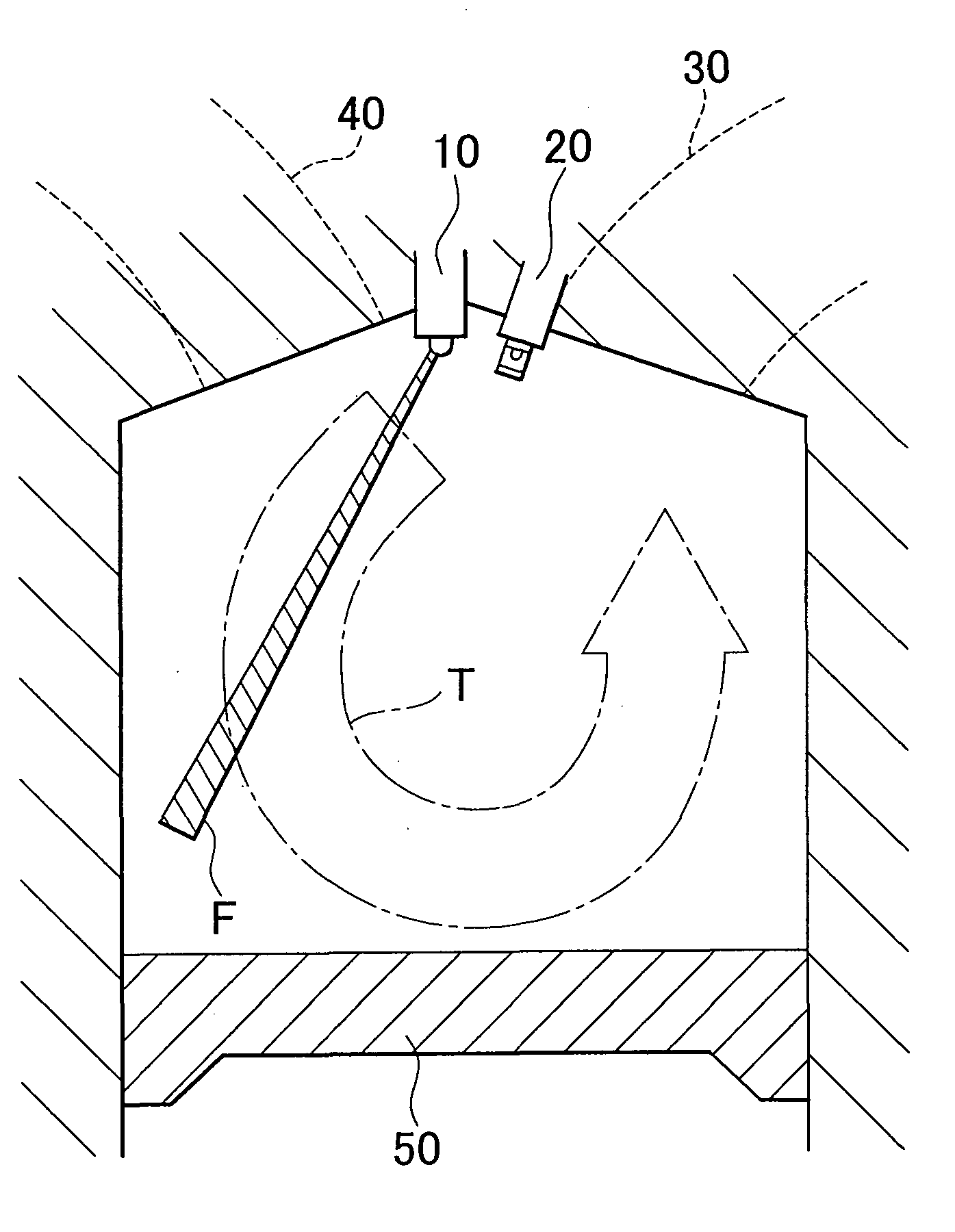
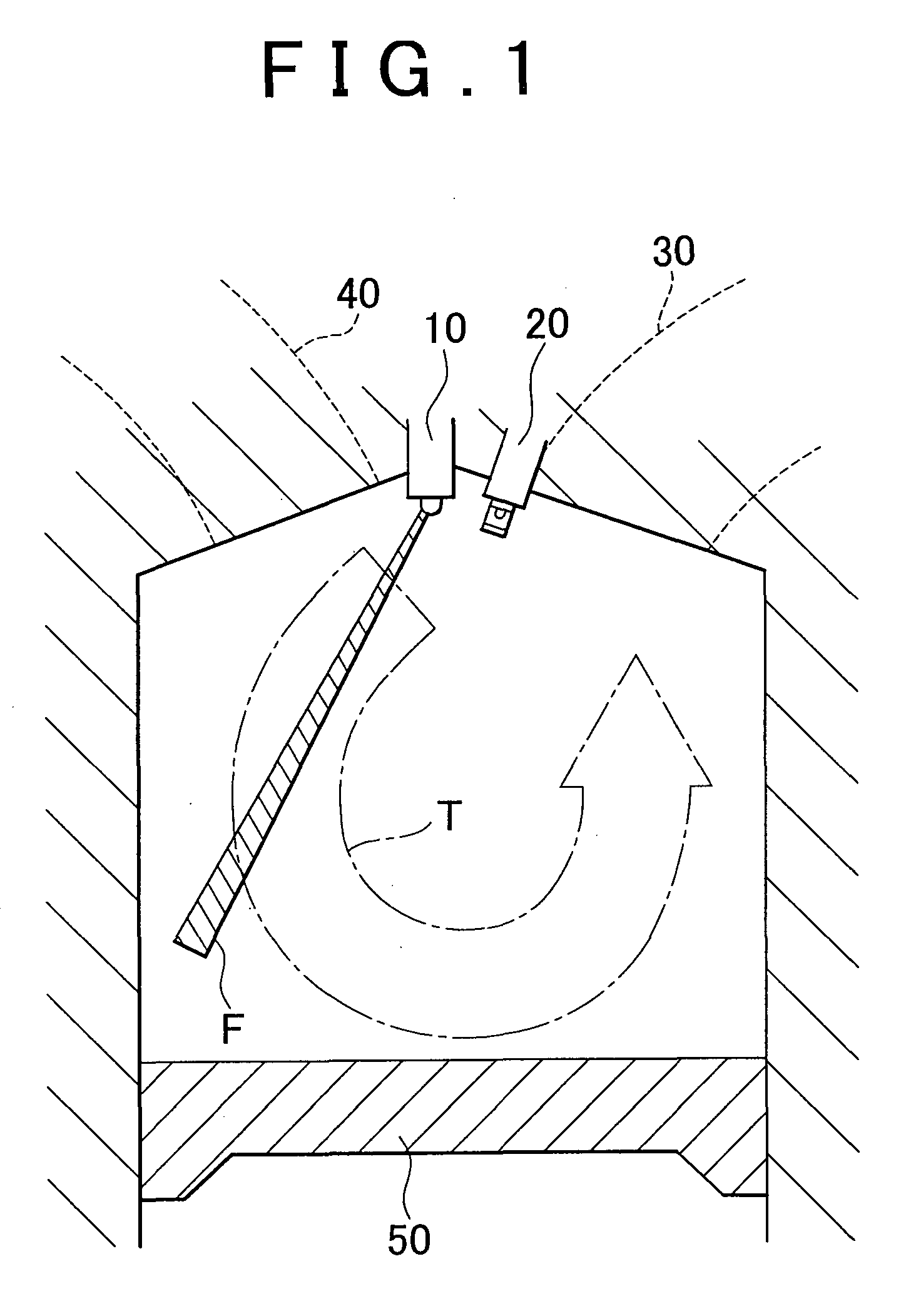
[0017]FIG. 1 is a vertical cross-sectional view schematically showing the structure of each cylinder of a direct injection spark ignition internal combustion engine that is controlled by a control apparatus according to an exemplary embodiment of the invention. Specifically, FIG. 1 shows a state immediately before the intake stroke bottom dead center on an intake stroke, which corresponds to the time of fuel injection for homogenous combustion. Referring to FIG. 1, a fuel injection valve 10 is provided at substantially the center of the upper area of the cylinder to inject fuel directly into the cylinder, and an ignition plug 20 is provided near the fuel injection valve 10 on the intake valve side thereof. FIG. 1 also shows a pair of intake ports 30 communicating with the inside of the cylinder via a pair of intake valves (not shown in the drawings), a pair of exhaust ports 40 communicating with the inside of the cylinder via a pair of exhaust valves (not shown in the drawings) and,...


PUM


Abstract

In a direct injection spark ignition internal combustion engine in which, after the engine has been started at a low temperature, the tumble flow is intensified in each cylinder by the fuel injected at a time near the intake stroke bottom dead center so that homogenous combustion is properly performed and additional fuel is then injected after the ignition time in order to increase the exhaust gas temperature, the thrust force of fuel injected from a fuel injection valve is adjusted in at least two levels such that the thrust force of the additional fuel becomes weaker than the thrust force of the fuel injected at the time near the intake stroke bottom dead center.

Description

BACKGROUND OF THE INVENTION[0001]1. Field of the Invention[0002]The invention relates to a control apparatus and a control method for a direct injection spark ignition internal combustion engine.[0003]2. Description of the Related Art[0004]A direct injection spark ignition internal combustion engine has been proposed which, in order to accelerate the warming-up of a catalyst unit of the exhaust system of the engine after starting the engine at a low temperature, increases the exhaust gas temperature by injecting additional fuel into each cylinder on a power stroke where combustion is being performed and thus maintaining combustion in the cylinder or in the exhaust manifold on an exhaust stroke (For example, refer to Japanese Patent Application Publication No. 2000-97076 (JP-A-2000-97076)).[0005]Meanwhile, if a tumble flow that is created in each cylinder on an intake stroke in a direct injection spark ignition internal combustion engine can be maintained until the latter half of a c...

Claims


Application Information

Patent Timeline
Patent Type & Authority Applications(United States)
IPC IPC(8): F02B3/00
CPCF02D41/0245F02D41/3047Y02T10/26F02D2041/389Y02T10/44F02D41/405Y02T10/12Y02T10/40F02D41/02F02D41/40F02D41/30
Inventor ASHIZAWA, TAKESHI
Owner TOYOTA JIDOSHA KK
Why Eureka
Try Eureka