Vehicle body structure

Inactive Publication Date: 2005-03-03
HONDA MOTOR CO LTD
View PDF7 Cites 28 Cited by
  • Summary
  • Abstract
  • Description
  • Claims
  • Application Information

AI Technical Summary

Benefits of technology

[0010] As a result, the beads increase the rigidity of the floor panel in the direction of a compressive load. In this manner, the rigidity of the floor panel against an impact energy at an offset collision is increased. The increased rigidity of the floor panel prevents production of creases in the floor panel. This limits the retreat of the floor frame member due to an impact energy, preventing deformation. The amount of retreat of the floor frame member joined to th

Problems solved by technology

The amount of retreat of the floor frame member joined to the floor panel is thus limite

Method used


Image

  • Vehicle body structure
  • Vehicle body structure
  • Vehicle body structure

Examples


Embodiment Construction

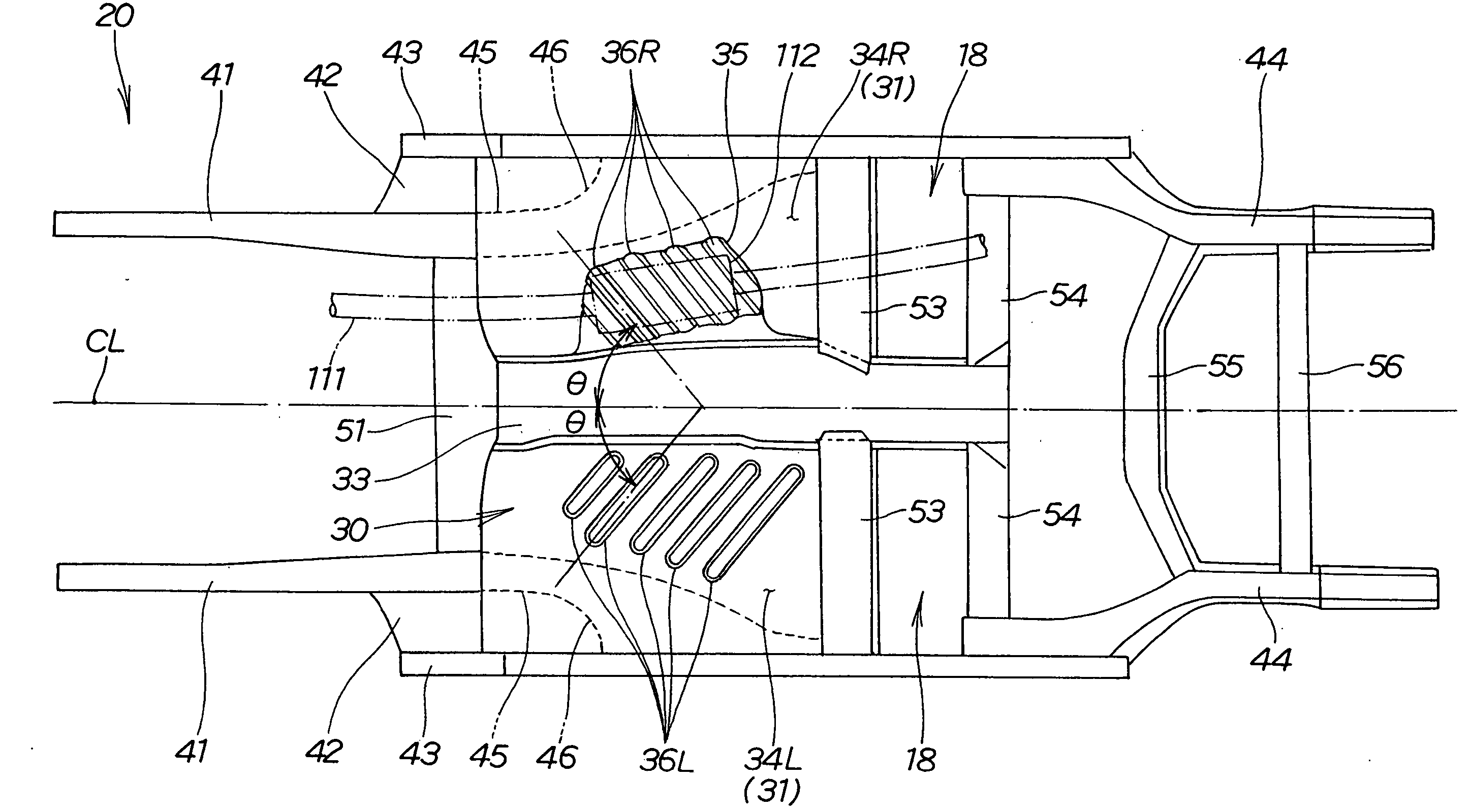
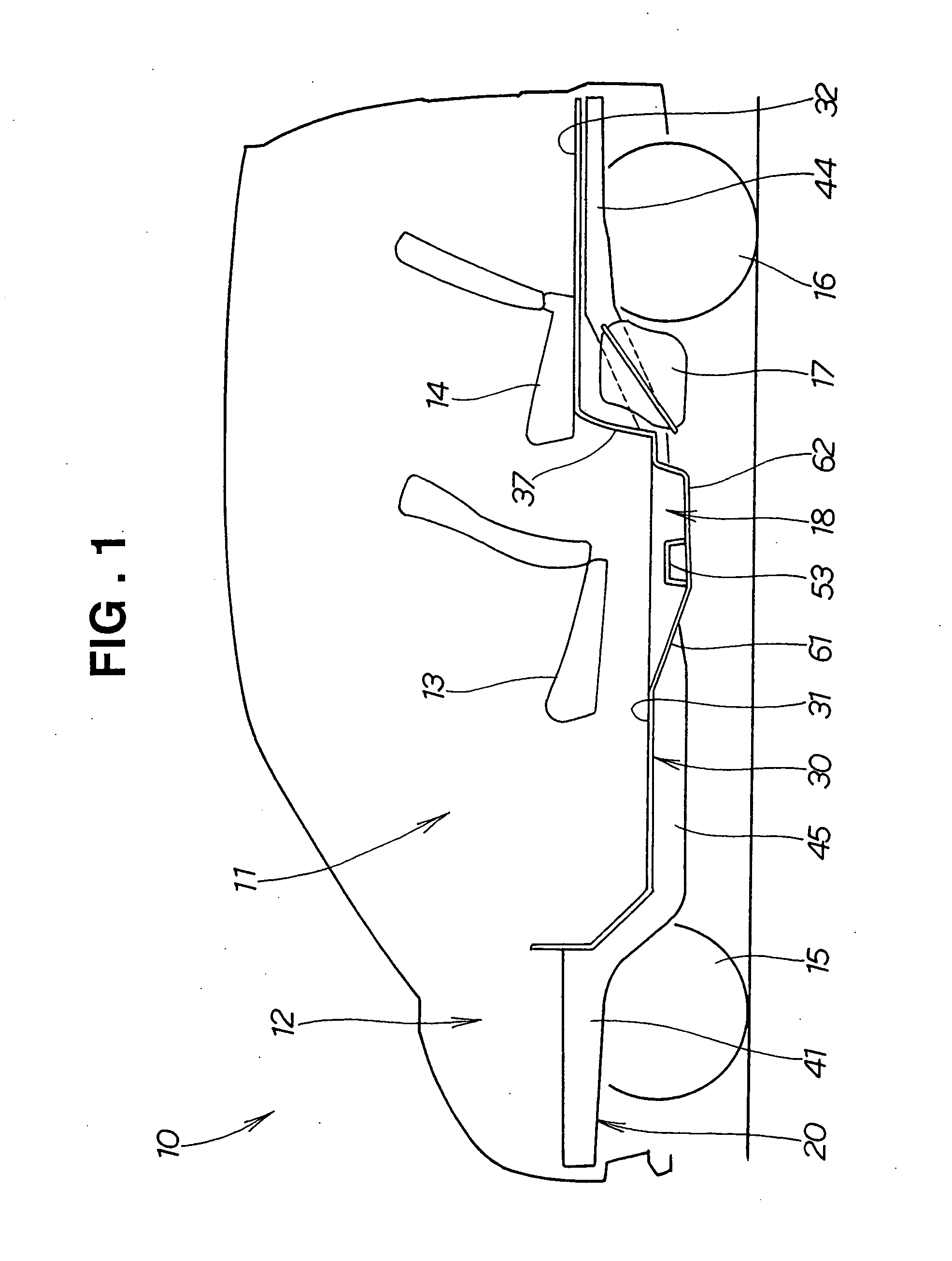
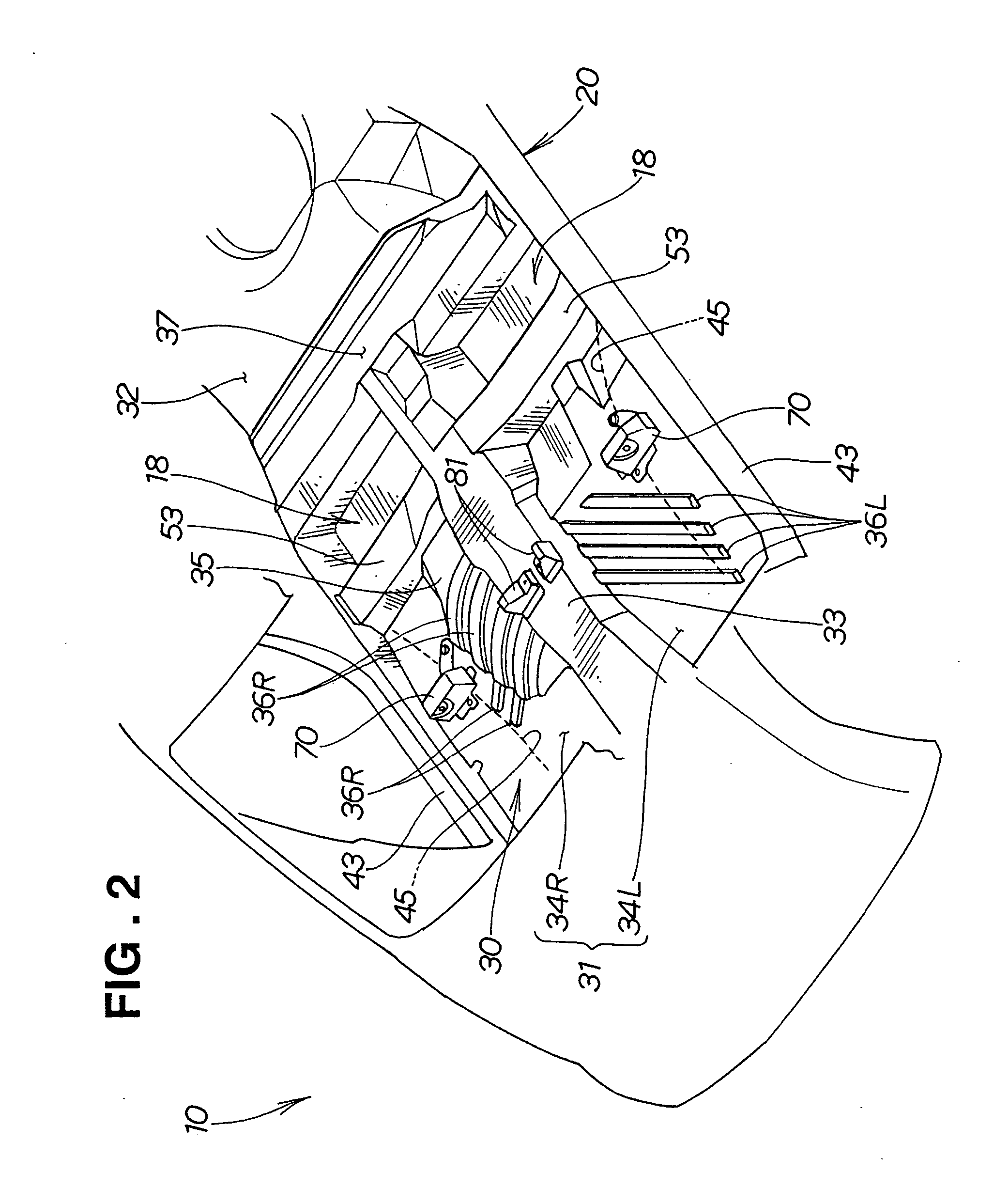
[0027] A vehicle 10 shown in FIG. 1 is a station wagon with a tail gate, having a passenger compartment 11 and an engine compartment 12 with no partition between the passenger compartment 11 and a rear trunk. The vehicle 10 has passenger seats (i.e., front seats 13 and rear seats 14) disposed in front and behind in the passenger compartment 11, and has a floor panel 30 extended over frame members of the body 20, a rear portion of which panel 30 forming a trunk portion.

[0028] Reference numeral 15 denotes a front wheel, and 16 a rear wheel.

[0029] The floor panel 30 includes a front floor panel 31 located at the front of the floor panel 30, and a rear floor panel 32 continued from the rear edge of the front floor panel 31, having a higher horizontal position than that of the front floor panel 31.

[0030] The left and right two front seats13 are disposed at approximately the center of the front floor panel 31. The left and right two rear seats 14 are disposed at the front of the rear f...


PUM


Abstract

A vehicle body structure with a floor panel having rigidity to withstand an impact energy at an offset collision of the vehicle is provided. The floor panel has a plurality of beads formed in a direction in which an impact energy acts. The beads are formed in the floor panel such that they extend obliquely rearward from left and right floor frame members toward the transversal center and are aligned longitudinally of the vehicle body.

Description

FIELD OF THE INVENTION [0001] The present invention relates generally to a vehicle body structure and, more particularly, to an improvement in a floor panel portion thereof BACKGROUND OF THE INVENTION [0002] A body structure for vehicles such as automobiles, designed to increase the rigidity of a floor panel portion is disclosed, for example, in Japanese Patent Laid-Open Publication No. 5-221342. The disclosed vehicle body structure will be described with reference to FIGS. 12 and 13 hereof. [0003] Referring to FIGS. 12 and 13, a vehicle 200 has a body 201 with a floor panel 204. The floor panel 204 has a floor tunnel 202 bulged toward a passenger compartment at a transversal center and extending longitudinally of the body. To the underside of the floor panel 204, a pair of left and right floor frame members 203, 203 extending longitudinally on the opposite sides of the floor tunnel 202 are joined. In the floor panel 204, a number of beads 205 extending transversely are formed at lo...

Claims


Application Information

Patent Timeline
IPC IPC(8): B62D21/15B62D25/20
CPCB62D21/157B62D25/2036B62D25/20B62D25/025
Inventor NAKAMURA, TADASHITOBA, YOSHIYUKI
Owner HONDA MOTOR CO LTD
Why Eureka
Try Eureka