Emergency brake warning lamp

A lighting and emergency technology, which is applied to vehicle components, optical signals, signal devices, etc., can solve problems such as vehicle collisions, insufficient braking safety distance, endangering the lives of drivers and passengers in the rear vehicle, etc., so as to reduce accidents and improve warnings Effect, the effect of increasing driving safety

Inactive Publication Date: 2010-03-10
YIH IND
View PDF0 Cites 19 Cited by
  • Summary
  • Abstract
  • Description
  • Claims
  • Application Information

AI Technical Summary

Problems solved by technology

[0003] However, the brake lights of general vehicles only have a constant light display mode
When the vehicle is running at high speed and the driver of the vehicle in front brakes urgently, the vehicle behind is at the same speed, so it is impossible to immediately determine whether the vehicle in front is in a normal braking state or an emergency braking state, so that the driver of the rear vehicle notices and brakes. Usually, because of insufficient braking safety distance, a vehicle collision event occurs, which endangers the lives of the driver of the vehicle behind and the passengers of the vehicle in question.

Method used


Image

  • Emergency brake warning lamp
  • Emergency brake warning lamp
  • Emergency brake warning lamp

Examples


Embodiment Construction

[0035] The above and other technical features and advantages of the present invention will be described in more detail below in conjunction with the accompanying drawings.

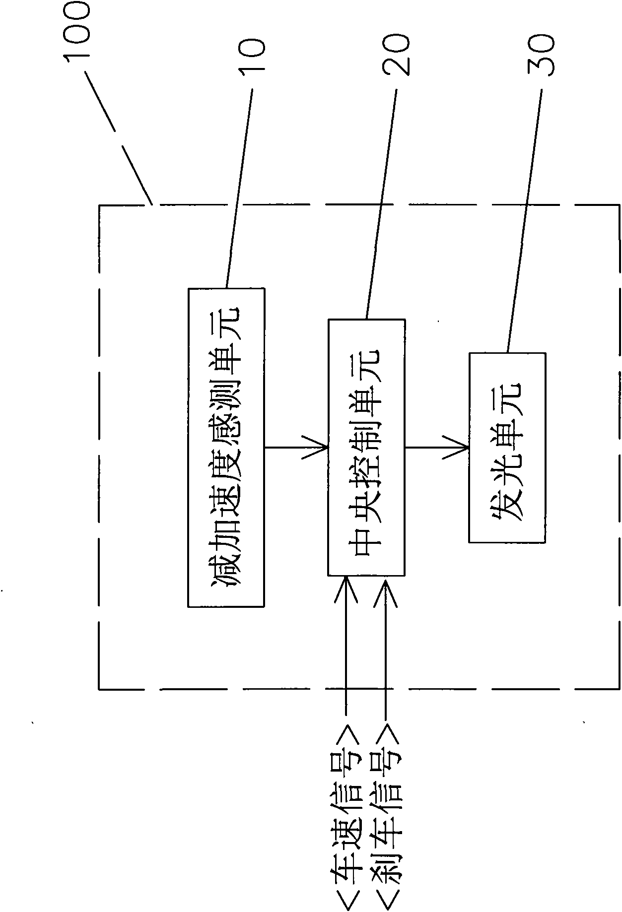
[0036] First, see figure 1 As shown, it is a structural block diagram of the first preferred embodiment of the emergency brake warning lamp of the present invention. In this preferred embodiment, the lamp 100 is arranged at the rear of the vehicle body, and can be used as a third brake lamp, a rear combination lamp (Rear Combination Lamp) and other warning lamps for braking. The lamp 100 is provided with a deceleration sensing unit 10 , a central control unit 20 and a light emitting unit 30 . in:

[0037] The deceleration sensing unit 10 is a circuit composed of sensors, and is electrically connected to the central control unit 20, to detect the deceleration (Deceleration) when the vehicle is braking, and simultaneously output the deceleration correspondingly Signal. The sensor can be implemented in th...


PUM


Abstract

The invention discloses an emergency brake warning lamp, which comprises a deceleration and acceleration sensing unit, a central control unit, and a luminous unit, wherein the deceleration and acceleration sensing unit senses the deceleration and acceleration when a vehicle is braked, and simultaneously correspondingly outputs signals; the central control unit is arranged in the lamp, is electrically connected with the deceleration and acceleration sensing unit, and correspondingly outputs driving signals when simultaneously receiving a speed signal and a brake signal of the vehicle and the signals of the deceleration and acceleration sensing unit; and the luminous unit is arranged in the lamp and electrically connected with the central control unit, so that the luminous unit is started bythe driving signals output by the central control unit and performs luminous display. By taking the speed signal, the brake signal and the deceleration and acceleration signals as judging conditions,the lamp has different display states such as a common brake state, an emergency brake state and the like to improve the warning effect on rear vehicles, increase driving safety and reduce the occurrence of accidents.

Description

technical field [0001] The invention relates to a warning lamp, in particular to an emergency brake warning lamp. Background technique [0002] According to the results of human factors engineering analysis, when the vehicle is driving at high speed, the driver at the rear will take about 1.2 to 2.0 seconds to judge the braking of the vehicle in front, and when the vehicle is driving at high speed, the vehicle in front brakes suddenly and undergoes a drastic deceleration change , the braking safety distance of the vehicle behind will be shortened. Furthermore, the faster the speed of the vehicle, the earlier the driver's required braking safety reaction time, and the required braking safety reaction distance will also increase accordingly. [0003] However, the brake lights of general vehicles only have a constant light display mode. When the vehicle is running at high speed and the driver of the vehicle in front brakes urgently, the vehicle behind is at the same speed, so...

Claims


Application Information

Patent Timeline
Patent Type & Authority Applications(China)
IPC IPC(8): B60Q1/44B60Q1/52
Inventor 林明峰简政嘉林建豪林锟祺
Owner YIH IND
Why Eureka
Try Eureka