Connector

A connector and adjacency technology, which is applied in the direction of connection, parts of the connection device, contact parts, etc., can solve the problems of long casing and large connector.

Inactive Publication Date: 2010-03-10
SUMITOMO WIRING SYST LTD
View PDF1 Cites 11 Cited by
  • Summary
  • Abstract
  • Description
  • Claims
  • Application Information

AI Technical Summary

Problems solved by technology

[0005] The thickness of the partition wall separating adjacent cavities from each other is greater, making the housing vertically longer and the connector overall larger

Method used


Image

  • Connector
  • Connector
  • Connector

Examples


Embodiment Construction

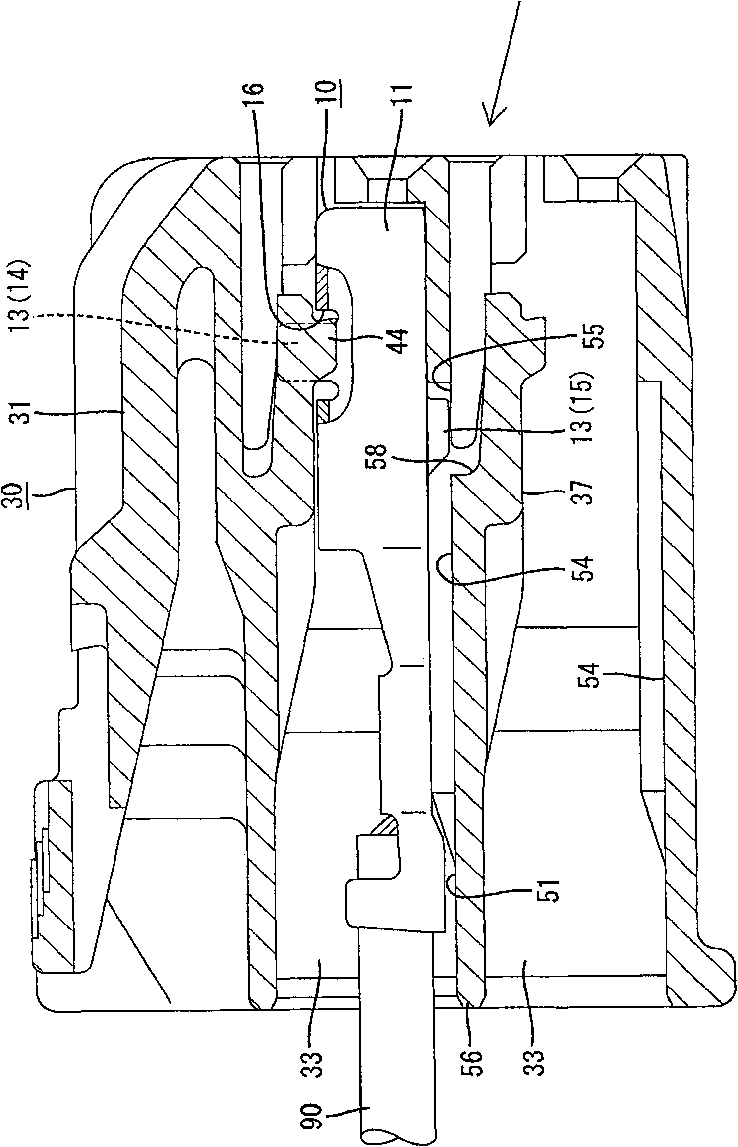
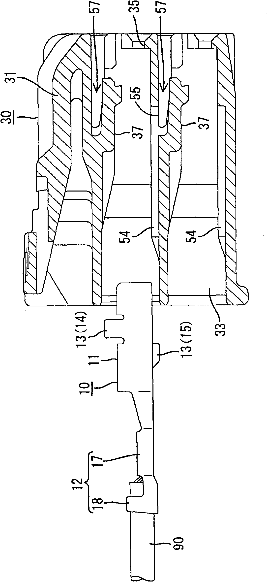
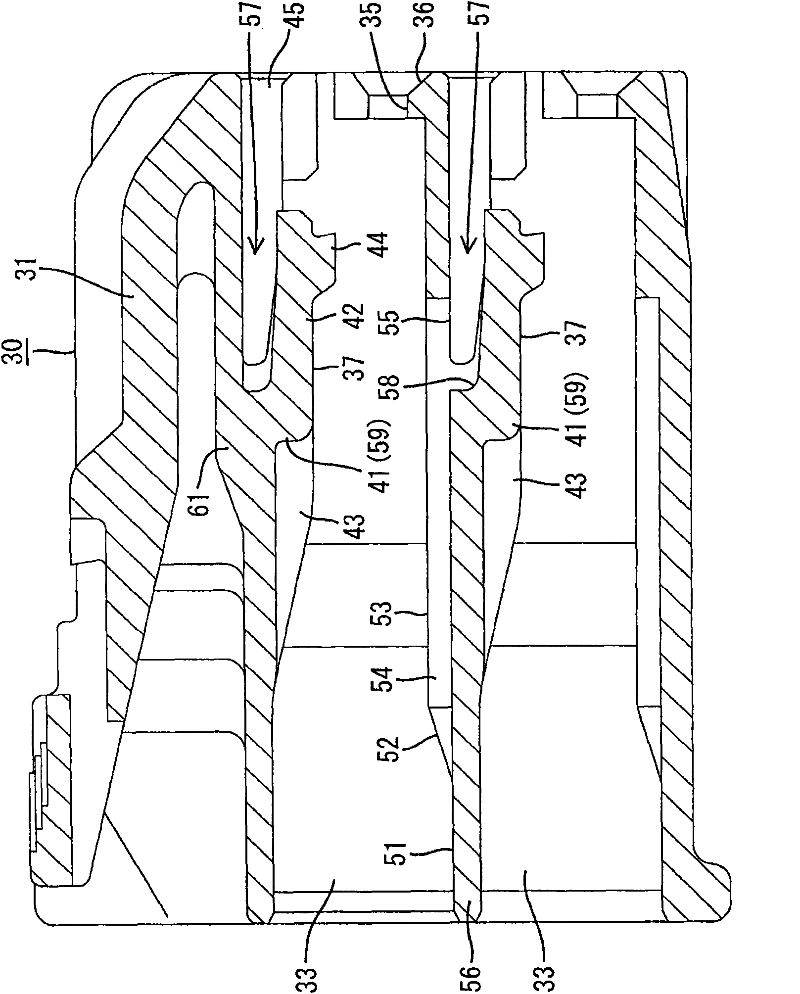
[0021] Refer below Figures 1 to 5 A first embodiment of the present invention is described. The connector of the first embodiment has a terminal fitting 10 and a housing 30 . The housing 30 and a mating housing not shown can be fitted to each other. Regarding the longitudinal direction described below, let the side of the housing 30 fitted in the mating housing be referred to as the front side.

[0022] The terminal fitting 10 is formed by bending a conductive metal plate. Such as figure 2 As shown, the terminal fitting 10 has a square column-shaped connecting portion 11 on its front side, and an open-tube-shaped tube portion 12 on its rear side. With the fitting between the housing 30 and the mating housing, the male tongues of the mating terminal fittings, not shown, are inserted into the connecting portion 11 from the front side. As a result, the two terminal lugs are electrically conductively connected to each other within the connection part 11 . The stabilizer 13...


PUM


Abstract

The invention provides a connector, which includes multiple terminal contactors, as well as a housing, and the housing has multiple cavities for respectively inserting terminal contactors therein. Theinvention is used for preventing the terminal contactor from reversely being inserted into the stabilizing piece in the housing and projecting from the terminal contactor. The stabilizing piece is recessedly formed at the inner wall of the cavity for being inserted into the guiding groove. The guiding groove of the housing has a communication mouth, and the communication mouth and the lower stepcavity which is next to the upper step cavity on which recessed guiding grooves are formed are communicated.The communication mouth is arranged for facing the upper surface of the spear rod on the upper surface of the inner wall formed on the lower step cavity.

Description

technical field [0001] The invention relates to a connector. Background technique [0002] The connector described in Patent Document 1 has a plurality of terminal fittings and a housing having a plurality of cavities into which the terminal fittings can be respectively inserted. A stabilizer for preventing reverse insertion of the terminal fitting into the cavity protrudes from the terminal fitting. A guide groove into which the stabilizing piece protrudes as the terminal fitting is inserted into the cavity is concavely formed on an inner wall of the cavity. [0003] The housing is provided with a partition wall that partitions the cavity in which the guide groove is concavely formed and the cavity adjacent to the cavity in which the guide groove is concavely formed are separated from each other. The guide groove is configured as a bottomed groove that extends longitudinally long and narrowly on the partition wall and is opened only on the rear surface of the housing. ...

Claims


Application Information

Patent Timeline
Patent Type & Authority Applications(China)
IPC IPC(8): H01R13/42H01R13/20H01R13/432
Inventor 陈重翰
Owner SUMITOMO WIRING SYST LTD
Why Eureka
Try Eureka