Vehicle brake hydraulic pressure control unit

a technology of hydraulic pressure control unit and brake, which is applied in the direction of braking system, mechanical equipment, servomotor components, etc., can solve the problems of deteriorating assembly efficiency, increasing the overall size of the vehicle brake pressure control unit, and generating looseness between the respective constituent parts, so as to reduce the size of the base body and reduce the vertical length of the base body. , the effect of deteriorating the assembling efficiency

Active Publication Date: 2013-02-05
HITACHI ASTEMO LTD
View PDF20 Cites 6 Cited by
  • Summary
  • Abstract
  • Description
  • Claims
  • Application Information

AI Technical Summary

Benefits of technology

[0011]The invention has been made with a view to solving these problems, and a problem that the invention is to solve is to provide a vehicle brake hydraulic pressure control unit which can realize the miniaturization of the unit and prevent the reduction in efficiency and accuracy with which constituent members are assembled together.
[0025]According to the configuration described above, since the housing mounting screw is mounted from the back surface side of the base body, the housing mounting screw does not interfere with a housing main body during the assembling work. Consequently, the installation position of the housing mounting screw can be located inwards, and the flange does not have to be made to project from an outermost circumferential surface of the control housing. Thus, the control housing and the base body can be made smaller in size, whereby a reduction in the overall size of the vehicle brake hydraulic pressure control unit can be realized.
[0026]In addition, since the housing mounting screw and the motor mounting screw are provided individually, the tolerance only has to be considered between the base body and the motor, and between the base body and the control housing, inside diameters of the through hole of the flange of the motor and the through hole of the base body can be made smaller than those of the vehicle brake pressure control unit of U.S. Pat. No. 6,260,582 B1, whereby the enlargement of the base body and the flange of the motor, the deterioration in assembling efficiency due to the increase in time for positioning the constituent members together and the radial looseness can all be prevented.
[0027]Furthermore, since the housing mounting screw and the motor mounting screw can be fastened from the same direction, the assembling efficiency is improved further.
[0033]According to the configuration described above, since the motor mounting screws can be fastened to the positions which are disposed in a point symmetry fashion about the motor bearing hole, the motor can be fixed in a stable state. Furthermore, the flange of the motor is not formed to project upwards and downwards of the motor, whereby the vertical length of the base body can be reduced.
[0034]According to the vehicle brake hydraulic pressure control unit of the invention, the size thereof can be reduced, and the deterioration in assembling efficiency with which the motor, the base body and the control housing are assembled together and the radial looseness therebetween after they have been assembled can be prevented.

Problems solved by technology

Because of this, the base body is also made large in size in a portion which corresponds to the flange, these leading to a problem that an increase in overall size of the vehicle brake pressure control unit.
In addition, in the event that the respective through holes are increased due to the tolerances, a certain length of time is necessary to position the respective members in a radial direction, this deteriorating the assembling efficiency, and furthermore, there has been caused a problem that looseness is generated between the respective constituent members after they have been assembled together.

Method used


Image

  • Vehicle brake hydraulic pressure control unit
  • Vehicle brake hydraulic pressure control unit
  • Vehicle brake hydraulic pressure control unit

Examples


Embodiment Construction

[0041]Hereinafter, a detailed explanation for carrying out the invention will be described with referring to the accompanying drawings.

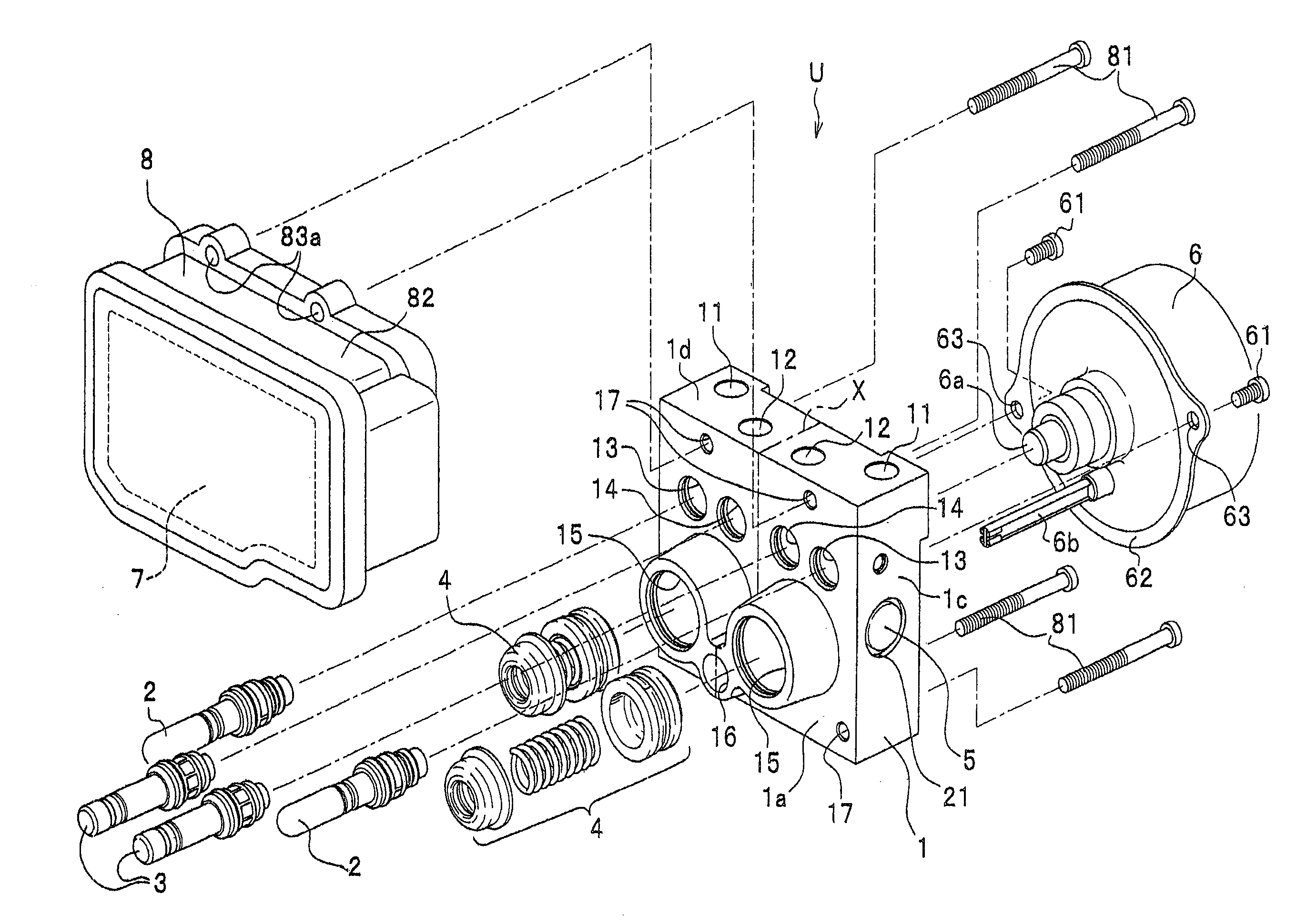
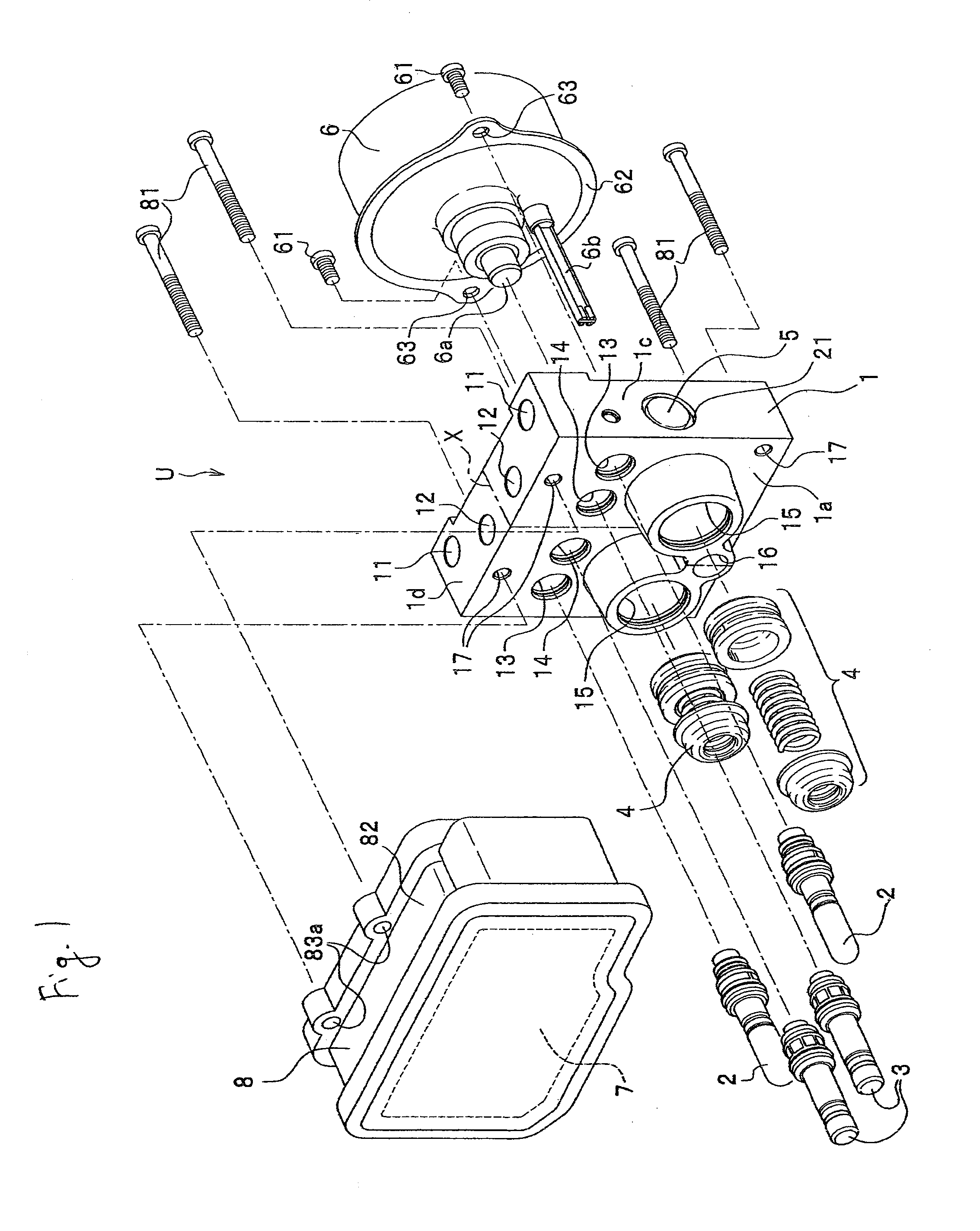
[0042]As shown in FIG. 1, a vehicle brake hydraulic pressure control unit (hereinafter, referred to as a “brake hydraulic pressure control unit”) U is such as to be suitable for a vehicle with a handlebar, and is configured to include a base body 1, solenoid valves 2, 3, reservoirs 4, a pump 5, a motor 6, an electronic control unit (a control unit) 7, and a housing (a control housing) 8. The housing 8 is assembled to a front surface 1a of the base body 1 and accommodates therein the electronic control unit 7. The motor 6 is assembled on to a back surface 1b of the base body 1 (refer to FIG. 3).

(Configuration of Vehicle Brake Hydraulic Pressure Control Unit)

[0043]Next, the construction of the brake hydraulic pressure control unit will be described. Note that when used in the following description, “lateral / laterally or horizontal / horizontally” and “up...


PUM


Abstract

A flange 62 having motor mounting through holes 63 is provided on a motor 6, motor mounting holes 19 are provided on a base body 1, so that motor mounting screw 61 are passed through the motor mounting through hole 63 from a back surface 1b side so as to be screwed into the motor mounting holes 19 to fix the motor 6 to the base body 1. Housing mounting holes 83 are provided on a control housing 8, housing mounting through holes 17 are formed on the base body 1 so as to be offset from portions which are in abutment with the flange 62, so that housing mounting screws 81 are passed through the housing mounting through holes 17 from the back surface 1b side so as to be screwed into the housing mounting holes 83 to fix the control housing 8 to the base body 1.

Description

BACKGROUND OF THE INVENTION[0001]1. Field of the Invention[0002]The present invention relates to a vehicle brake hydraulic pressure control unit.[0003]2. Description of Related Art[0004]Various types of vehicle brake hydraulic pressure control units have been proposed, and among them, for example, there are vehicle brake hydraulic pressure control units which are described in Japanese Patent Unexamined Publication JP-A-07-47945 and U.S. Patent Examined Publication U.S. Pat. No. 6,260,582 B1.[0005]In a vehicle brake hydraulic pressure control unit described in the JP-A-07-47945, a flange having through holes is provided on a motor, and by inserting screws from the motor side through the through holes so as to be screwed into a base body, the motor is fixed to the base body. On the other hand, a flange having through holes is also provided on a control housing, and by inserting screws from the control housing side through the through holes so as to be screwed into the base body, the c...

Claims


Application Information

Patent Timeline
Patent Type & Authority Patents(United States)
IPC IPC(8): B60T8/40
CPCB60T8/368F15B13/0842
Inventor KODAMA, TAKURONAKAMURA, MOTOYASU
Owner HITACHI ASTEMO LTD
Why Eureka
Try Eureka