Planar multi-channel slow wave structure

A slow-wave structure and multi-channel technology, which is applied to the circuit components of time-of-flight tubes, can solve the problem of incompatibility between operating bandwidth and gain, achieve high gain, reduce equipment volume, and increase gain.

Active Publication Date: 2018-08-31
UNIV OF ELECTRONIC SCI & TECH OF CHINA
View PDF7 Cites 6 Cited by
  • Summary
  • Abstract
  • Description
  • Claims
  • Application Information

AI Technical Summary

Problems solved by technology

[0006] However, in the existing planar slow wave structure, the problem of in

Method used


Image

  • Planar multi-channel slow wave structure

Examples


Example Embodiment

[0018] The specific embodiments of the present invention will be described below in conjunction with the accompanying drawings, so that those skilled in the art can better understand the present invention. It is important to note that in the following description, when detailed descriptions of known functions and designs may dilute the main content of the present invention, these descriptions will be omitted here.
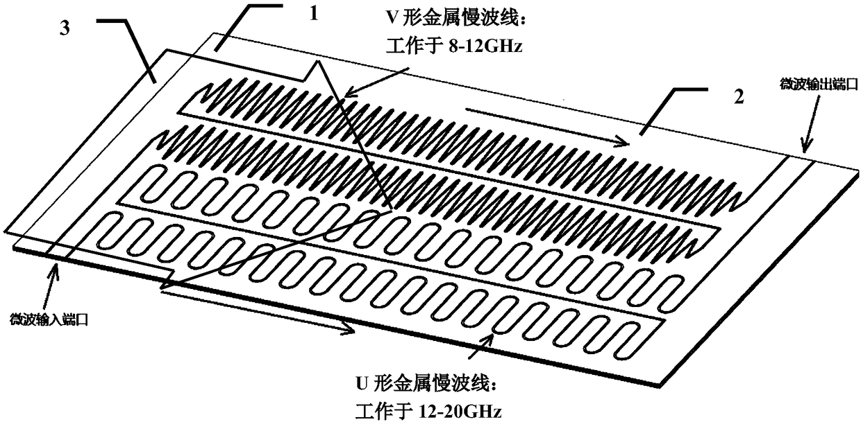
[0019] figure 1 It is a schematic structural diagram of a specific implementation of the planar multi-channel slow wave structure of the present invention.

[0020] In this embodiment, as figure 1 As shown, the planar multi-channel slow-wave structure includes a dielectric base plate 1, four metal slow-wave wires 2 with the same transmission direction, arranged one after another and aligned in parallel, and four metal slow-wave wires 2 with the same transmission direction are processed by etching, welding, etc. On the dielectric base plate 1, these metal slow wave lin...


PUM


Abstract

The invention discloses a planar multi-channel slow wave structure. By processing four metal slow wave lines which have the same transmission direction, are sequentially arranged and aligned in parallel on a medium substrate, the same working voltage is simultaneously loaded, and the same electron beam is used. Among the four metal slow wave lines, the identical slow wave lines in pairs are connected in series in an end-to-end manner to form two sets of the metal slow wave lines connected in series, so that an amplified electromagnetic wave signal is returned to the start place of beam-wave interaction, namely, the position before the electron beam deceleration, and the beam-wave interaction is performed again to achieve the purpose of further amplifying the electromagnetic signal, therebysignificantly increasing the gain. At the same time, since the two sets of the metal slow wave lines connected in series operate in different frequency bands, the working bandwidth can be significantly improved without affecting the efficiency of the beam-wave interaction. Compared with the scheme using multiple traveling wave tubes, the planar multi-channel slow wave structure of the invention can greatly reduce the equipment size.

Description

technical field [0001] The invention belongs to the technical field of vacuum electronic devices, and more specifically relates to a planar multi-channel slow wave structure in vacuum electronic devices such as traveling wave tubes and klystrons. Background technique [0002] Vacuum electronic devices are a class of power amplifiers that convert the kinetic energy of high-energy electron beams into electromagnetic wave energy after the interaction between high-energy electron beams and electromagnetic wave signals, including traveling wave tubes, klystrons, return wave tubes, and gyrotrons. The slow wave structure is the core component of the traveling wave tube, and its structure determines the main working performance of the traveling wave tube. In a slow wave structure, the electromagnetic wave phase velocity is less than the speed of light in vacuum. The electron beam can be accelerated to slightly greater than the phase velocity of the electromagnetic wave by a suitabl...

Claims


Application Information

Patent Timeline
IPC IPC(8): H01J23/24
CPCH01J23/24H01J2223/24
Inventor 崔灿曹华王战亮宫玉彬黄华许雄
Owner UNIV OF ELECTRONIC SCI & TECH OF CHINA
Why Eureka
Try Eureka