Holographic optical waveguide device for three-dimensional dynamic display and augmented reality display equipment

A three-dimensional dynamic and optical waveguide technology, applied in optics, optical components, instruments, etc., can solve problems in the field of unapplied augmented reality technology, and achieve the effects of real-time dynamic display process, simple calculation of holographic devices, and shortened longitudinal length

Active Publication Date: 2020-11-17
谷东科技有限公司
View PDF7 Cites 5 Cited by
  • Summary
  • Abstract
  • Description
  • Claims
  • Application Information

AI Technical Summary

Problems solved by technology

However, the current computational holography is mainly used for displaying directly through the LCD screen, and has not been applied to the field of augmented reality technology.

Method used


Image

  • Holographic optical waveguide device for three-dimensional dynamic display and augmented reality display equipment
  • Holographic optical waveguide device for three-dimensional dynamic display and augmented reality display equipment
  • Holographic optical waveguide device for three-dimensional dynamic display and augmented reality display equipment

Examples


Embodiment Construction

[0048]Reference will now be made in detail to the exemplary embodiments, examples of which are illustrated in the accompanying drawings. When the following description refers to the accompanying drawings, the same numerals in different drawings refer to the same or similar elements unless otherwise indicated. The implementations described in the following exemplary examples do not represent all implementations consistent with the present disclosure. Rather, they are merely examples of apparatuses and methods consistent with aspects of the present disclosure as recited in the appended claims.

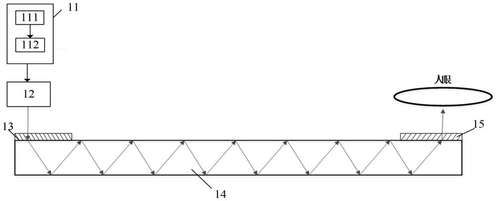
[0049] figure 1 is a schematic structural diagram of a holographic optical waveguide device for three-dimensional dynamic display according to an exemplary embodiment, as shown in figure 1 As shown, the holographic optical waveguide device includes: an optical-mechanical system 11, a lens system 12, a coupling-in multiplexing volume holographic grating 13, a waveguide plate 14 and an o...


PUM


Abstract

The invention relates to a holographic optical waveguide device for three-dimensional dynamic display and augmented reality display equipment. The holographic optical waveguide device comprises an optical-mechanical system which comprises a laser illumination system and a micro-display, wherein the micro-display is used for loading a three-dimensional computed hologram obtained after the wavefrontcoding of a three-dimensional scene, light waves irradiated to the micro-display are modulated by the laser illumination system according to the three-dimensional computed hologram, and the modulatedlight waves carrying three-dimensional scene wavefront information distribution enter a lens system; the lens system which is used for filtering the light wave carrying the three-dimensional scene wavefront information distribution and then emitting the light wave into a multiplexing volume holographic grating; the multiplexing volume holographic grating which is used for coupling the light wavecarrying the three-dimensional scene wavefront information distribution into a waveguide plate; the waveguide plate which transmits the light wave carrying the three-dimensional scene wavefront information distribution to a coupled-out multiplexing body holographic grating in a total reflection mode; and the coupled-out multiplexing volume holographic grating which is used for coupling the light wave carrying the three-dimensional scene wavefront information distribution out to human eyes.

Description

[0001] The present invention claims the priority of the Chinese patent application CN202010418635.9, and the content described in the specification, drawings and claims of the priority document is incorporated into the specification of the present invention in its entirety and is regarded as a part of the original description of the specification of the present invention. The applicant further declares that the applicant has the right to amend the description and claims of the present invention based on the priority document. technical field [0002] The present disclosure relates to the technical field of augmented reality, in particular to a holographic optical waveguide device for three-dimensional dynamic display and an augmented reality display device. Background technique [0003] Near-eye display means that while the observer is viewing real objects outside, information such as images or data superimposed in the real environment can also be viewed. It provides the func...

Claims


Application Information

Patent Timeline
Patent Type & Authority Applications(China)
IPC IPC(8): G02B27/01
CPCG02B27/0172G02B2027/0174
Inventor 李艳崔海涛钱进雍海波
Owner 谷东科技有限公司
Why Eureka
Try Eureka