Combined steaming oven

A combined, steam oven technology, applied to steam cooking utensils, roasters/barbecue grids, household appliances, etc.

Inactive Publication Date: 2010-03-17
马克斯·梅尔
View PDF8 Cites 7 Cited by
  • Summary
  • Abstract
  • Description
  • Claims
  • Application Information

AI Technical Summary

Problems solved by technology

Combi-steam ovens suitable for this have not yet appeared according to the applicant's knowledge

Method used


Image

  • Combined steaming oven
  • Combined steaming oven
  • Combined steaming oven

Examples


Embodiment Construction

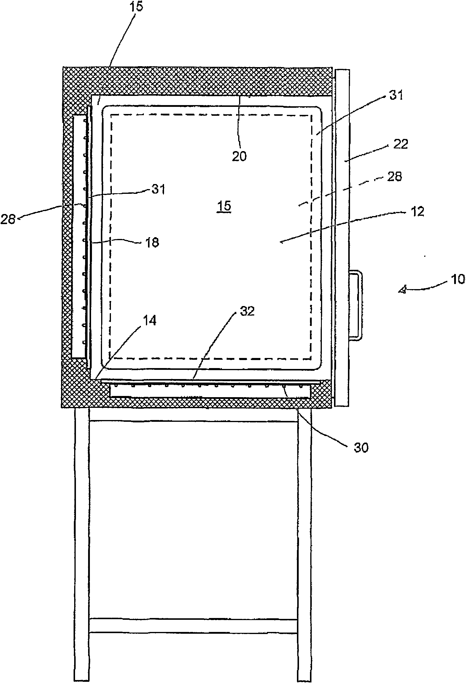
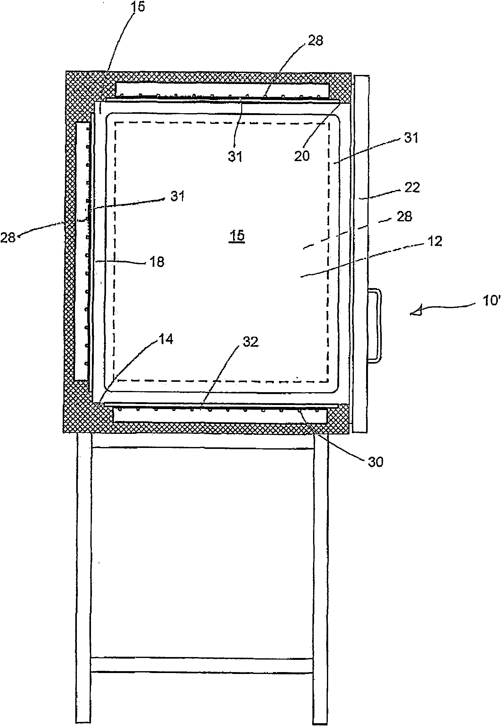
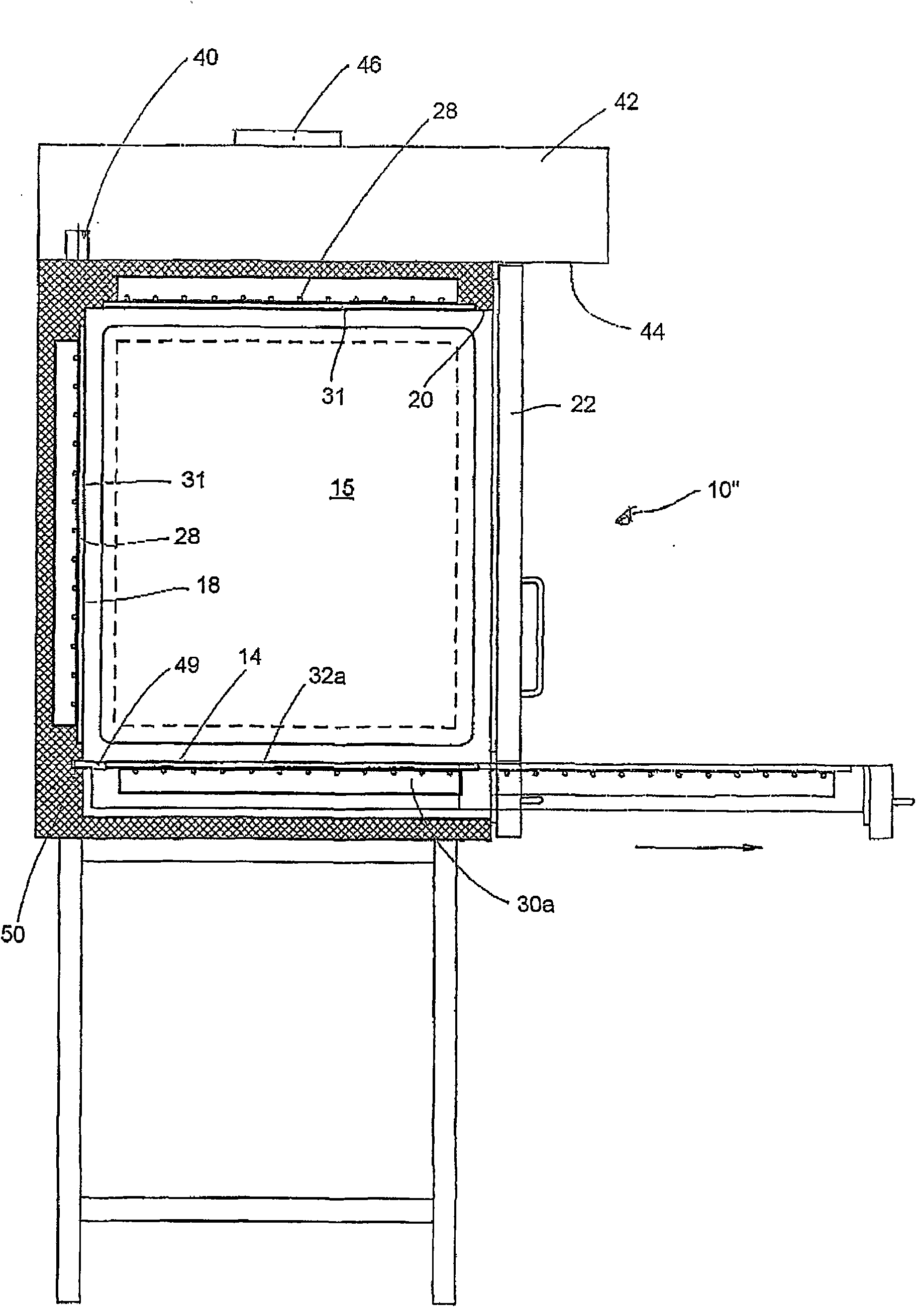
[0027] figure 1 A first embodiment of a combi-steam oven according to the invention is shown, which is indicated as a whole by 10 . In the first embodiment and in the embodiments described subsequently, the combi-steamer 10 is a so-called combi-steamer, that is to say a combination of a steam cooking device and an oven. The combi-steam oven 10 has a cooking chamber 12 which is outwardly defined by a bottom 14, two side walls 15 and 16 (the latter only in Figure 4 Visible in the view of ), the rear wall 18 and the upper wall 20 and the front side door 22 are bounded. The steam generator 24 and the optional blower 26 are only Figure 4 visible in , so will combine Figure 4 They are described in detail in the third embodiment of a combi-steam oven 10 ″ shown in . In the prior art mentioned at the beginning, the bottom 14 in combi-steam ovens is usually a continuous bottom on which Unlike the prior art, where a second heating device located in the cooking chamber is arranged...


PUM


Abstract

The invention discloses a combined steaming oven (10') with a cooking chamber. The cooking chamber is outwards defined through a bottom (14), walls (15, 16, 18 and 20) and a door (22). The cooking chamber (12) is provided with a steam generator and a first heating device (28) which is arranged on at least one of the walls (15, 16, 18 and 20). The bottom (14) is provided with a second heating device (30). Both the two heating device (28 and 30) are arranged outside the cooking chamber (12). The bottom (14) is constructed as a cooking area (32) provided with the second heating device (30). The walls (15, 16, 18 and 20) are constructed as a heating area (31) provided with the first heating device (28) respectively. The cooking area (32) can be pulled out from the cooking chamber (12) in a drawer mode. Therefore, when the cooking area (32) is positioned inside or outside the cooking chamber (12), dishes can be prepared on the cooking area (32).

Description

technical field [0001] The invention relates to a combi-steam oven comprising: a cooking chamber bounded outwards by a bottom, a wall and a front side door; a steam generator; a first heating device arranged on at least one of said walls and a second heating device arranged on the bottom. Background technique [0002] A known combi-steam oven of this type (DE 201 05 820 U1) allows cooking with hot air and / or steam. A combination steamer is usually a combination steam cooking appliance and an oven. It is either grilled or cooked with steam. Dishes to be cooked can be simply steamed, in which water is repeatedly sprayed in, for example at 100° C. In known combi-steam ovens, the sprayed-in water will be evaporated by the first heating means. The first heating device is installed in the cooking chamber on the inside of its wall and surrounds a blower which circulates the steam generated here in the cooking chamber. Certain food items such as pizza, baked cakes, vegetable pa...

Claims


Application Information

Patent Timeline
IPC IPC(8): A47J27/04A47J37/06
Inventor 马克斯·梅尔
Owner 马克斯·梅尔
Why Eureka
Try Eureka