
Drawer for furniture

A technology for drawers and furniture, which is applied to drawers, household utensils, furniture parts, etc. It can solve problems such as unsatisfactory pulling performance, loss of back space, and inability to pull out drawers.

Inactive Publication Date: 2006-11-01
PAUL HETTICH
View PDF0 Cites 4 Cited by
  • Summary
  • Abstract
  • Description
  • Claims
  • Application Information

AI Technical Summary

Problems solved by technology

However, the way of achieving the purpose of this type of drawer is not optimal as a lot of back space is lost and the pull performance is foreseeably unsatisfactory as the drawer cannot be fully extracted from the body of the furniture

Method used


Image

  • Drawer for furniture
  • Drawer for furniture
  • Drawer for furniture

Examples


Embodiment Construction

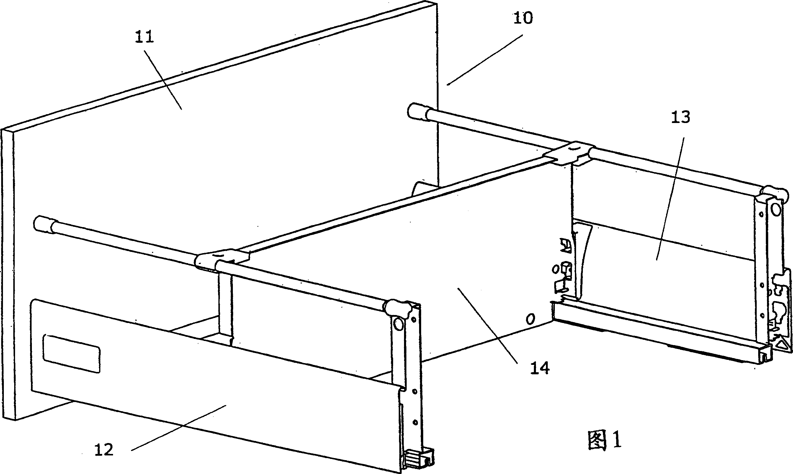
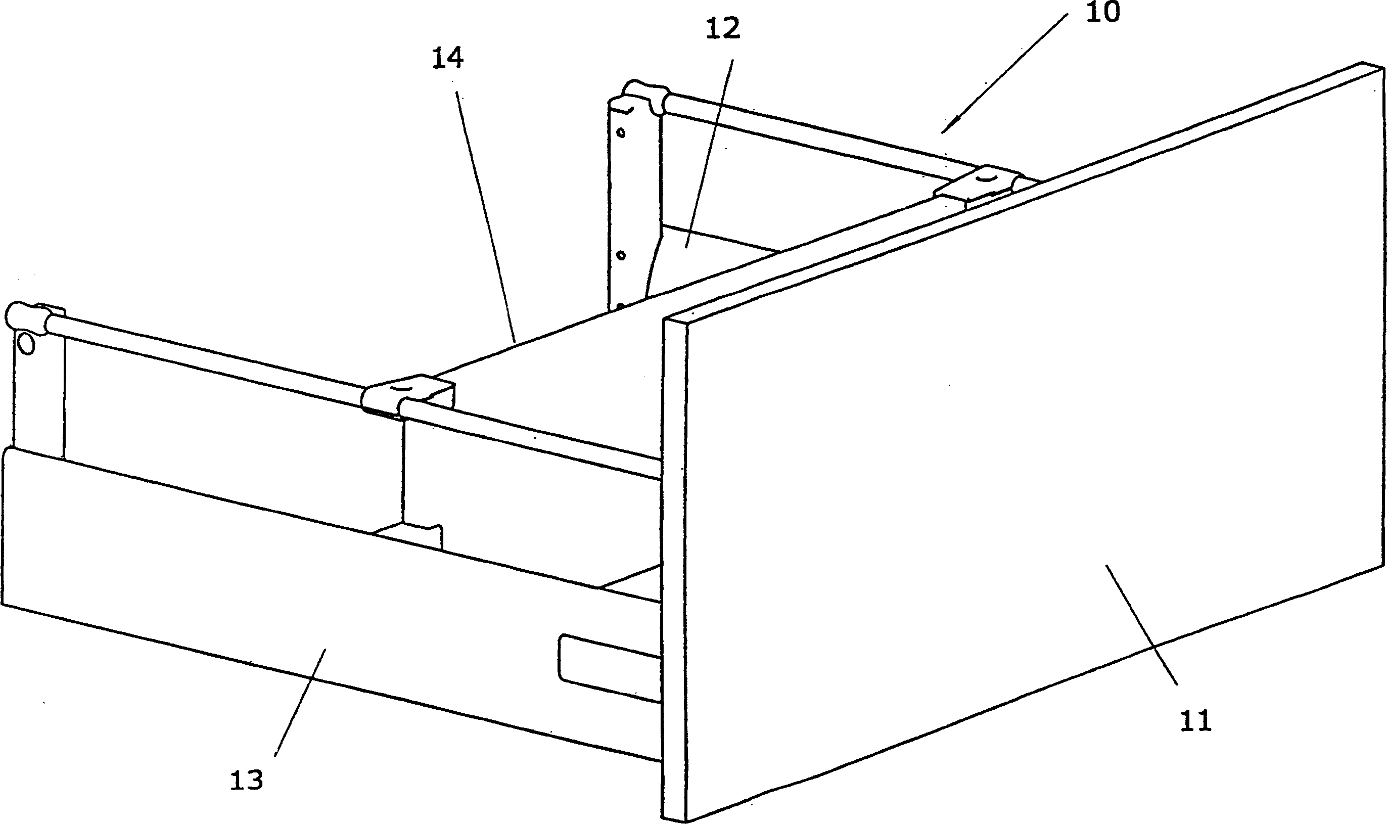
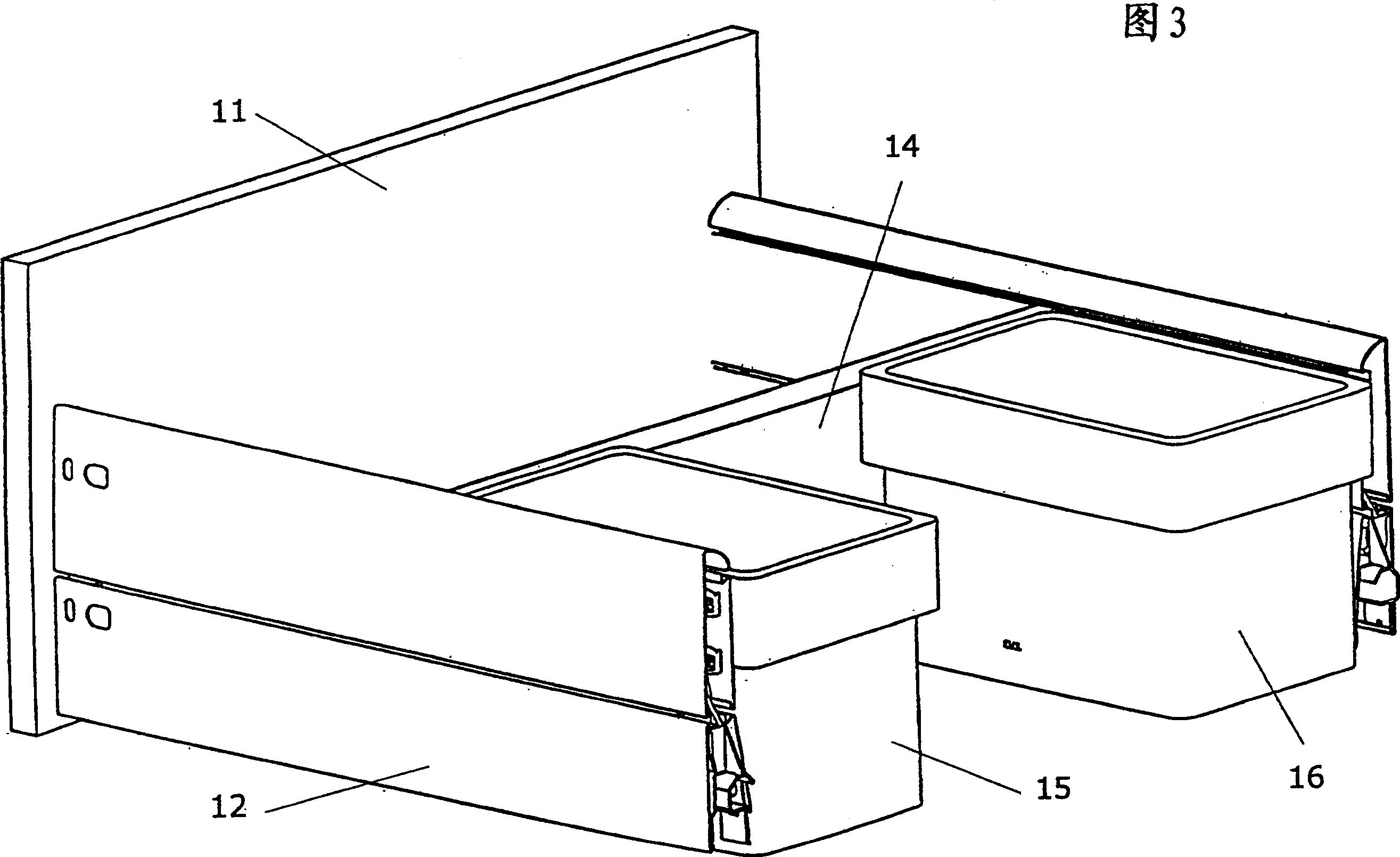
[0022] The drawer 10 shown in FIGS. 1-5 includes: a front baffle 11, a bottom plate 22 (FIG. 7); two side plates 12, 13 and a rear wall 14. The two side plates 12, 13 are laterally connected to the front baffle 11 and maintained perpendicular thereto. As clearly shown in FIGS. 1-5, using a pull rail including a rail system, the drawer 10 can be pulled out and retracted relative to the furniture body. The pulling system corresponds to an embodiment in which the drawer and the furniture body have the same depth.

[0023] As clearly shown in Figure 1, the distance between the front baffle 11 and the rear wall 14 is significantly smaller than the length of each side plate 12, 13, that is, the rear wall 14 and the opposite side of the front baffle 11 The edge of the bottom plate 22 is offset in a direction toward the front baffle 11 with respect to the rear surface of each of the side plates 12 and 13 opposite to the front baffle 11. Thus, in the area of ​​the height of the drawer 10, ...


PUM


Abstract

The drawer box is constructed so that the back wall (14) and the edge of the base remote from the front panel (11) are off-set towards the front panel from the rear end faces of the side rails (12,13) remote from the front panel. A shelf or container can be fitted by a holder at the back of the drawer and each holder can be formed as a hook so that the shelf can hang thereon. The drawer box is designed for a sink cupboard.

Description

Technical field [0001] The invention relates to a drawer for a piece of furniture. The drawer can be fixed and moved relative to the furniture body by using a pull rail. The drawer is provided with: a front baffle, a bottom plate, two upright side plates perpendicular to the front baffle, and a rear wall that is parallel to the front baffle and spaced a certain distance. Background technique [0002] In a piece of furniture in the form of a sink cabinet, there is a problem that a washbasin or a plurality of washbasins extend into the interior of the furniture body. In addition, the water supply line and the drain line are installed in the sink cabinet. Usually, hot water storage units or drain floor drains are also installed in the sink cabinet. The exact installation location of these devices is not pre-defined, so the interior of the sink cabinet is not optimally utilized. If a drawer of a typical design is used, then the rear wall of the drawer must be installed accordingly, s...

Claims


Application Information

Patent Timeline
Patent Type & Authority Applications(China)
IPC IPC(8): A47B88/04
CPCA47B77/18A47B88/994A47B88/90
Inventor R·米特尔蒂斯
Owner PAUL HETTICH
Learn More