
Visible light communication system using single light source

A visible light communication and visible light technology, applied in the field of visible light communication, can solve problems such as inability to send data

Inactive Publication Date: 2010-03-17
KK TOSHIBA
View PDF4 Cites 20 Cited by
  • Summary
  • Abstract
  • Description
  • Claims
  • Application Information

AI Technical Summary

Problems solved by technology

[0007] However, in a visible light communication system using a single light source, since transmission data is superimposed on the visible light emitted from one communication device side, the other communication device side cannot transmit data using only its reflected light.

Method used


Image

  • Visible light communication system using single light source
  • Visible light communication system using single light source
  • Visible light communication system using single light source

Examples


Embodiment Construction

[0016] Embodiments of the present invention will be described below with reference to the drawings.

[0017] (Structure of Visible Light Communication System)

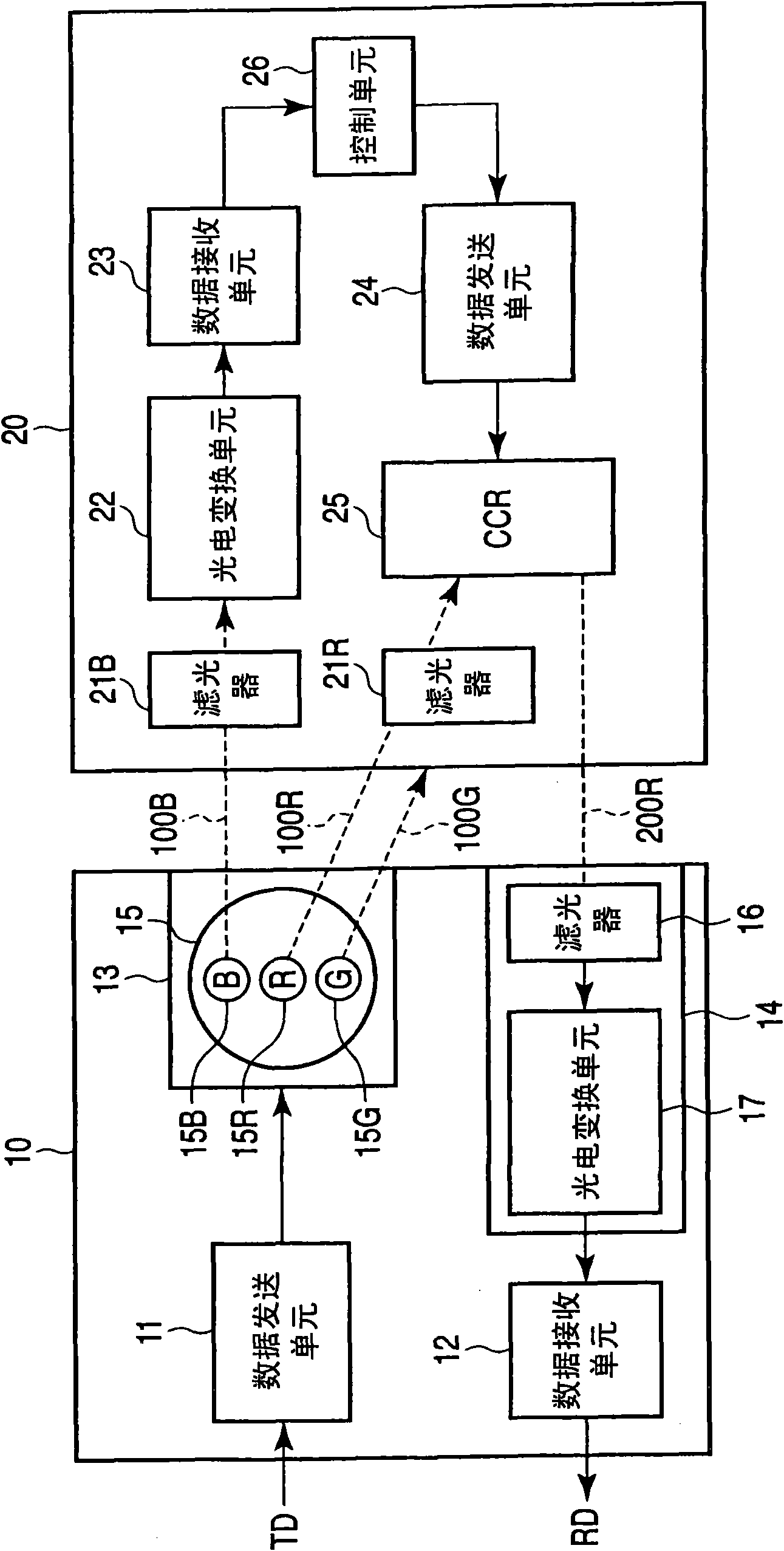
[0018] figure 1 It is a block diagram for explaining the structure of the visible light communication system of this embodiment. like figure 1 As shown, the visible light communication system of this embodiment includes one visible light communication device 10 and the other visible light communication device 20 , and realizes bidirectional communication using visible light.

[0019] In this embodiment, one visible light communication device 10 is, for example, a communication device incorporated in lighting equipment fixed to a ceiling or the like in a building, and is described as a visible light transceiver device 10 for convenience. The other visible light communication device 20 is, for example, a communication device incorporated in a mobile phone or the like, and is described as a mobile terminal 20 for conve...


PUM


Abstract

The invention provides a visible-light communications system in which bidirectional visible-light communication is performed between a visible-light communications device (10) and a mobile terminal (20). The device (10) has one light source (13). The mobile terminal (20) has a retroflection unit (25). The mobile terminal (20) further has optical filters (21B and 21R). The optical filter (21B) extracts a visible light beam (100B) modulated with the data transmitted from the visible-light communications device (10). The optical filter (21R) extracts a visible light beam (100R) that will be usedas a retroflection light beam that is not modulated.

Description

[0001] This application is based on and claims priority from Japanese Priority Patent Application No. 2008-235140 filed on September 12, 2008, the latter application being incorporated herein by reference in its entirety. technical field [0002] The present invention relates to a visible light communication technology that realizes two-way communication using visible light. Background technique [0003] In recent years, the development of a visible light communication technology using visible light from a light source using a light emitting diode (light emitting diode) element (hereinafter sometimes referred to as LED) or the like has been advanced. In order to realize two-way communication using visible light, in addition to the system having light sources on both the transmitting side and the receiving side, a hybrid system combining infrared communication or radio wave communication with visible light communication has been proposed. [0004] However, the hybrid method s...

Claims


Application Information

Patent Timeline
Patent Type & Authority Applications(China)
IPC IPC(8): H04B10/10H04B10/11H04B10/112H04B10/524H04B10/54H04J14/00H04J14/02
CPCH04B10/1149H04B10/2587H04B10/116
Inventor 铃木胜宜岛田重人
Owner KK TOSHIBA
Learn More