
Method for regulating and generating scanning signal as well as driving device applying same

A scanning signal and driving device technology, applied in the field of scanning driving, can solve the problems of cost and area increase, serious scanning signal attenuation, etc., and achieve the effect of avoiding image sticking

Inactive Publication Date: 2010-03-31
INTEGRATED SOLUTIONS TECH
View PDF0 Cites 8 Cited by
  • Summary
  • Abstract
  • Description
  • Claims
  • Application Information

AI Technical Summary

Problems solved by technology

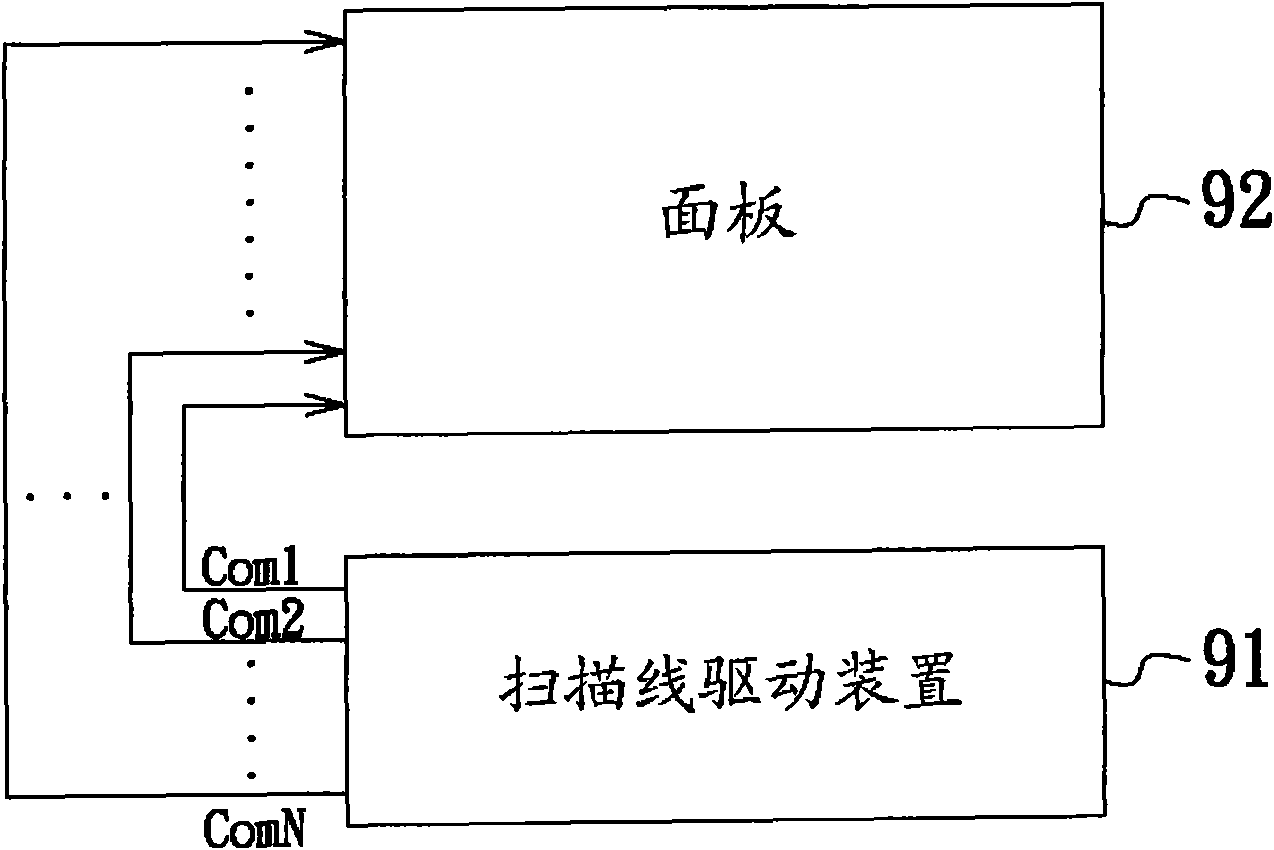
However, due to the different lengths of the traces between the scanning line driving devices 91 and the panel 92, the non-ideal effects (such as loading effects, etc.) on each scanning line are not the same, resulting in different degrees of influence of each scanning line on the scanning signal. Attenuation, that is, the scan line Com1 closest to the panel 92 and with the shortest trace will have the least impact on the scan signal; conversely, the scan line ComN with the longest trace from the panel 92 will have the most severe attenuation on the scan signal
[0004] Therefore, the existing solution is to gradually widen the width of each scan line along with the distance of the lines to reduce the signal attenuation caused by non-ideal effects. However, due to the variety of panels and the width of the scan lines in It is fixed and cannot be changed at the time of manufacture. Therefore, the existing methods cannot be changed for various panels, and when the panel size becomes larger and larger, the width of the traces will also increase with the increase in the number of scanning lines. Wider and wider, leading to an increase in cost and area, so the existing method still needs to be improved

Method used


Image

  • Method for regulating and generating scanning signal as well as driving device applying same
  • Method for regulating and generating scanning signal as well as driving device applying same
  • Method for regulating and generating scanning signal as well as driving device applying same

Examples


Embodiment Construction

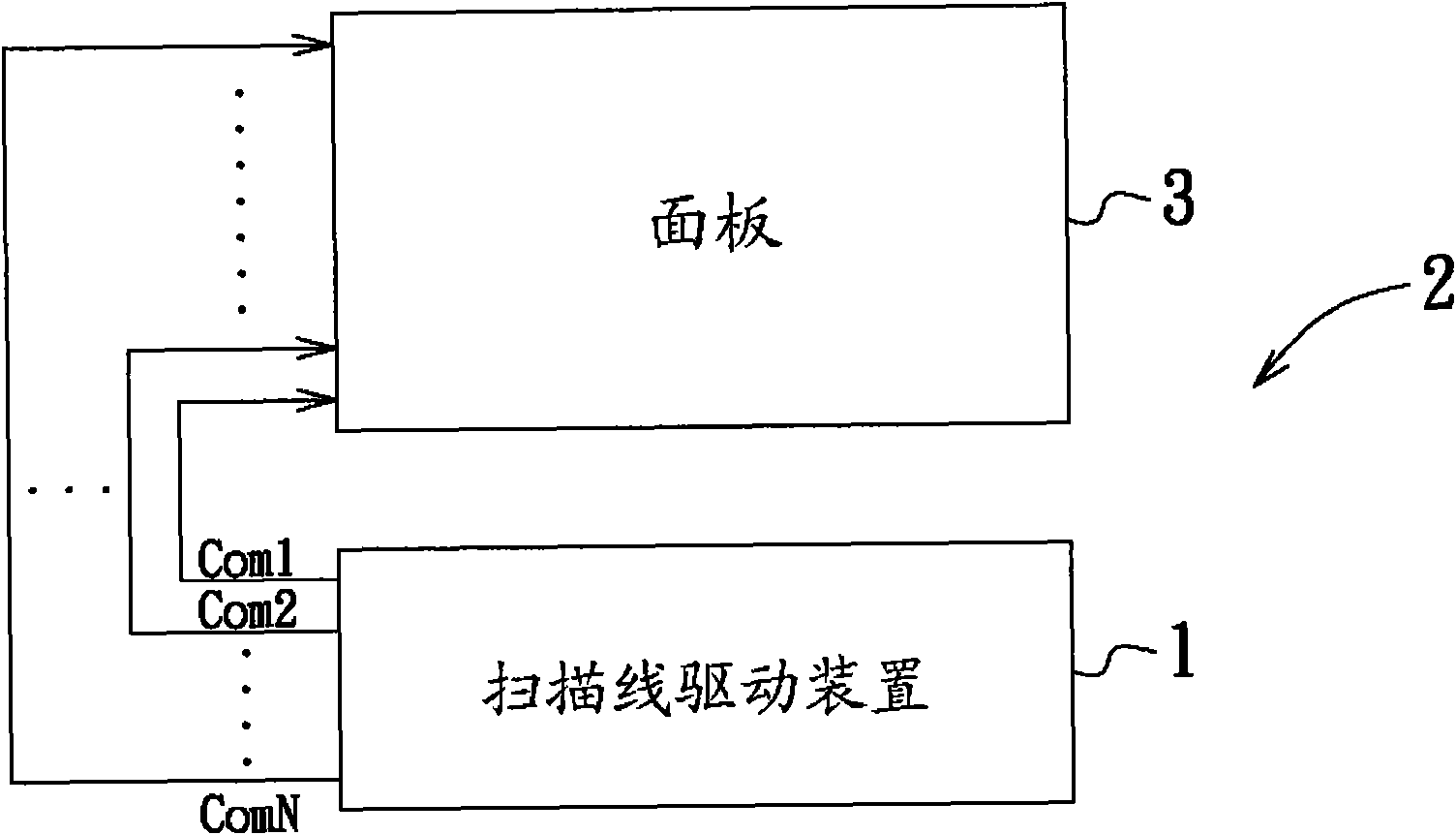
[0037] The present invention will be described in detail below in conjunction with the accompanying drawings and embodiments.

[0038] refer to figure 2 The scanning line driving device 1 of the present embodiment is applied to a super twisted nematic (Super Twisted Nematic, referred to as STN) liquid crystal display 2, and is used to respectively output a scanning signal to a plurality of scanning lines connected to a display panel 3, That is to say, if the panel 3 has N display columns, the scanning line driving device 1 needs N scanning lines (Com1-ComN) to be connected to each display column in a one-to-one correspondence, so as to transmit scanning signals to the display column through these scanning lines. The N bars of panel 3 display columns.

[0039] Since the trace lengths of the scan lines from the scan line driving device 1 to the panel 3 are different, each scan line is subjected to different non-ideal effects (such as loading effects, etc.), resulting in differen...


PUM


Abstract

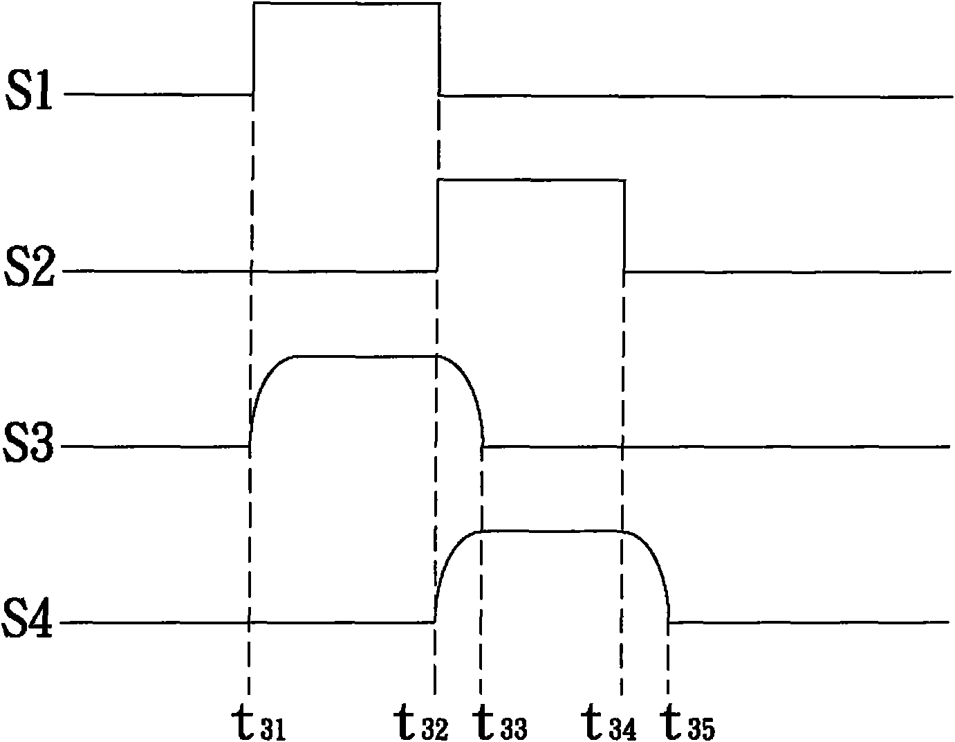
The invention relates to a method for regulating and generating scanning signals as well as a driving device applying same, which is applied to a scanning line driving device, and the scanning line driving device is used to respectively output a scanning signal to multiple scanning lines connected with a display panel. The method comprises the following steps: firstly measuring a starting point ofa rising edge and a finishing point of a falling edge of a duty cycle of each scanning signal; then computing the difference between the finishing point of the falling edge of the duty cycle of the previous scanning signal and the starting point of the rising edge of the duty cycle of the next scanning signal; and finally, regulating the duty cycle of each scanning signal according to the difference to bring forward the finishing point of the duty cycle of the previous scanning signal to the starting point of the duty cycle of the next scanning signal. By adopting the invention, non mutual overlapping of the two scanning signals is achieved so as to avoid the occurrence of crosstalk interference.

Description

technical field [0001] The invention relates to a scanning driving method, in particular to a scanning driving method of a display. Background technique [0002] Due to the characteristics of light weight, small size and low power consumption, liquid crystal displays have gradually replaced traditional cathode ray tubes (CRTs), and have already become mainstream products in the display market. Among various liquid crystal displays, Super Twisted Nematic (abbreviated as STN) liquid crystal display has higher contrast than twisted nematic (Twisted Nematic, TN) liquid crystal display, and its manufacturing cost is much lower. Based on thin film transistors (TFTs), it is widely used in electronic products such as mobile phones and digital cameras. [0003] refer to figure 1 , is the connection relationship between the scanning line driving device 91 and the panel 92 in the existing STN type liquid crystal display. If the panel 92 has N display columns, the scanning line drivin...

Claims


Application Information

Patent Timeline
IPC IPC(8): G09G3/36
Inventor 林柏志何政哲
Owner INTEGRATED SOLUTIONS TECH
Learn More