Wafer bonding apparatus

A wafer bonding and wafer technology, applied in electrical components, semiconductor/solid-state device manufacturing, circuits, etc., can solve problems such as conflict with fixing devices, and achieve the effect of reducing manufacturing costs and shortening process time

Inactive Publication Date: 2010-03-31
SAMSUNG ELECTRONICS CO LTD
View PDF1 Cites 10 Cited by
  • Summary
  • Abstract
  • Description
  • Claims
  • Application Information

AI Technical Summary

Problems solved by technology

In conventional wafer bonding setups, the compression device may interfere with the fixture

Method used


Image

  • Wafer bonding apparatus
  • Wafer bonding apparatus
  • Wafer bonding apparatus

Examples


Embodiment Construction

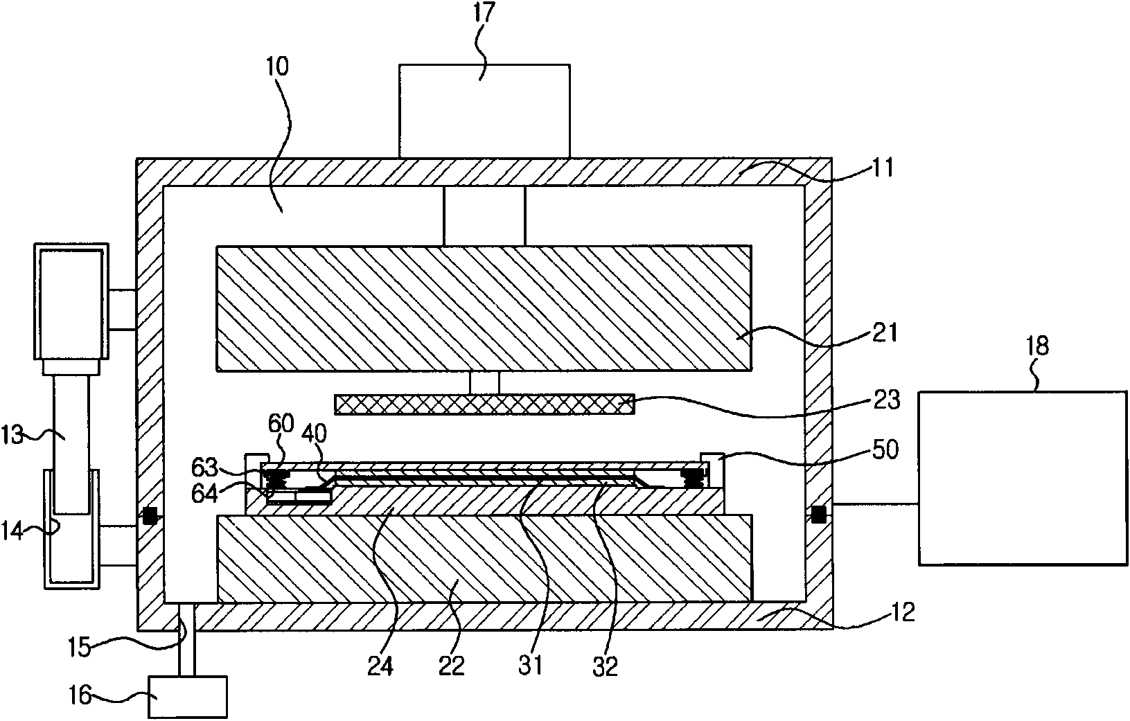
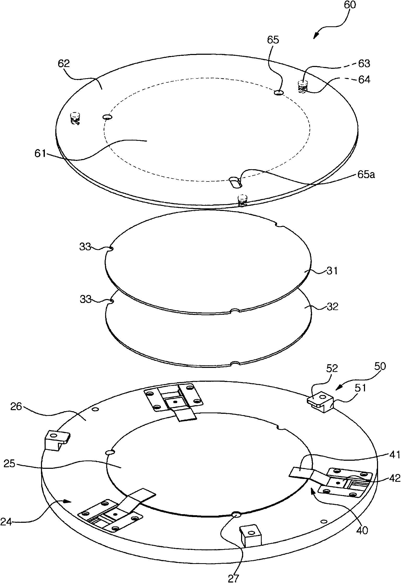
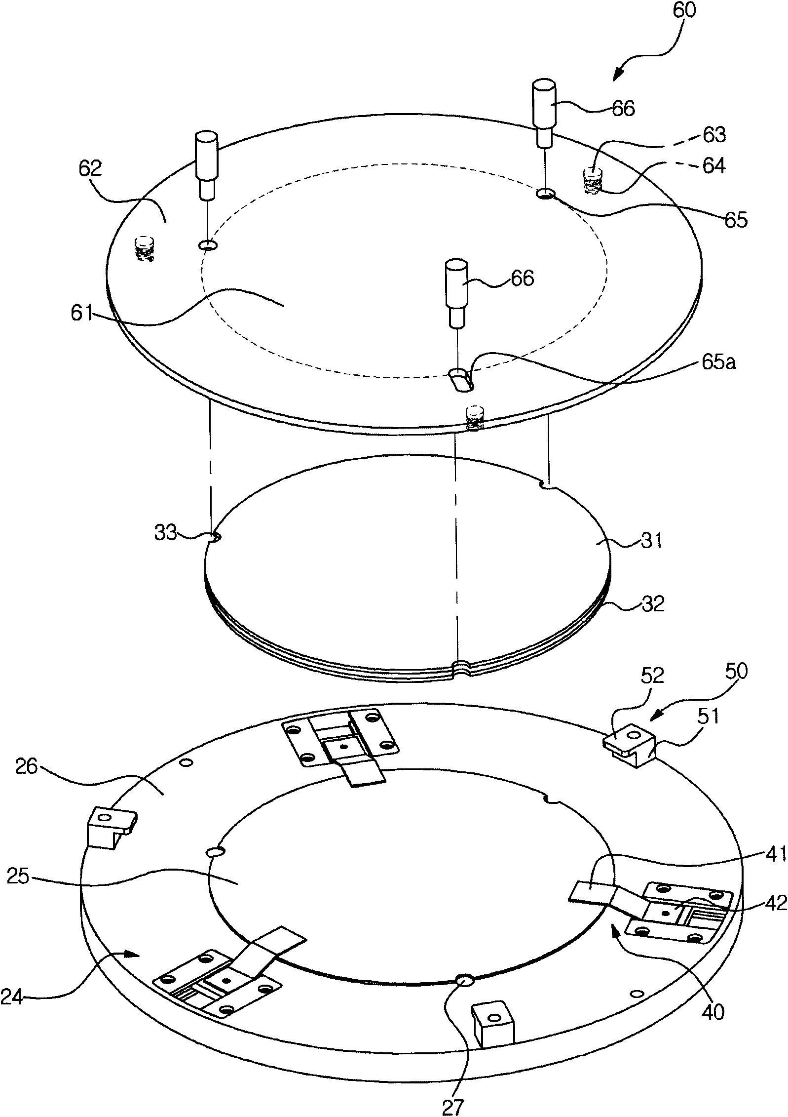
[0048] Exemplary embodiments of the present invention will now be described more fully with reference to the accompanying drawings, in which exemplary embodiments of the invention are shown. However, this invention may be embodied in different forms and should not be construed as limited to the embodiments set forth herein. Rather, these embodiments are provided so that this disclosure will be thorough and complete, and will fully convey the scope of the invention to those skilled in the art. In the drawings, the size of components may be exaggerated for clarity.

[0049] It will be understood that when an element or layer is referred to as being "on," or "connected to" or "coupled to" another element or layer, that element or layer may Directly on, or directly connected to or bonded to, another element or layer, or intervening elements or layers may also be present. In contrast, when an element is referred to as being "directly on" or "directly connected to" or "directly coup...


PUM


Abstract

It is an aspect of the present invention to provide a wafer bonding apparatus having a pressing apparatus configured to press wafers fixed in a fixing apparatus, wherein the fixing apparatus is configured to allow the pressing apparatus to press the wafers without interference. The wafer bonding apparatus may include an upper wafer and a lower wafer, a support member configured to support the upper wafer and the lower wafer, a push member on the upper wafer, and a fixing apparatus configured to fix the push member to the support member, wherein the push member includes a fixing part extendingoutward from a periphery of the upper wafer, and the fixing apparatus is coupled to the fixing part. It is also an aspect of the present invention to provide a method for bonding wafers.

Description

technical field [0001] The following description relates to a wafer bonding apparatus and a method of bonding wafers. More specifically, the following description relates to a wafer bonding apparatus capable of maintaining an aligned state of a wafer by fixing the wafer. Background technique [0002] The wafer bonding process may include the following steps: pre-bonding wafer cleaning, sample loading, wafer bonding, and substrate removal. [0003] Wafer bonding equipment can be used in the wafer bonding process. A wafer bonding apparatus may be used to bond a pair of wafers to each other using an adhesive interposed between the pair of wafers. A wafer bonding apparatus may be provided with a vacuum chamber and an aligner. The wafers may be aligned in an aligner, loaded into a vacuum chamber, and bonded to each other in the vacuum chamber. [0004] Wafers transferred from the aligner into the vacuum chamber may be misaligned. Therefore, a fixture can be installed in the ...

Claims


Application Information

Patent Timeline
Patent Type & Authority Applications(China)
IPC IPC(8): H01L21/00H01L21/02
CPCH01L21/67092H01L21/2007H01L21/68
Inventor 申宰奉李炳俊石承大崔丞佑金重铉洪相一
Owner SAMSUNG ELECTRONICS CO LTD
Why Eureka
Try Eureka