A connector

A connector and ground connection technology, applied in the direction of connecting components, welding equipment, auxiliary welding equipment, etc., can solve the problem of the limitation of the applied force and achieve a good air suction effect

Inactive Publication Date: 2010-03-31
G·G·H·斯瓦斯布鲁克
View PDF2 Cites 2 Cited by
  • Summary
  • Abstract
  • Description
  • Claims
  • Application Information

AI Technical Summary

Problems solved by technology

[0018] Thus, while in principle UK Patent No. 2359113 could be used in a wide range of situations, in practice its use is limited by the amount of force that can be applied

Method used


Image

  • A connector
  • A connector
  • A connector

Examples


Embodiment Construction

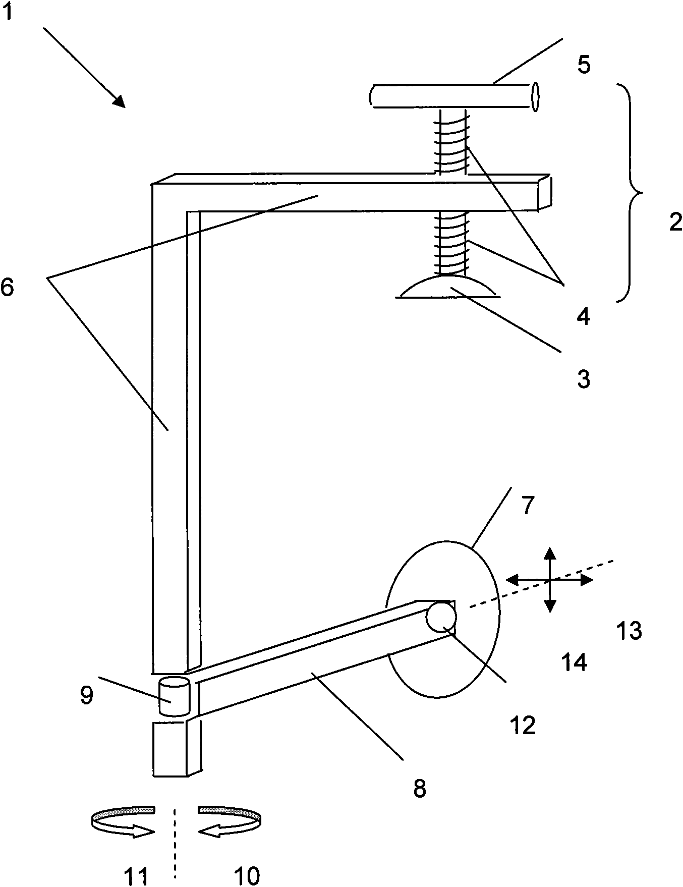
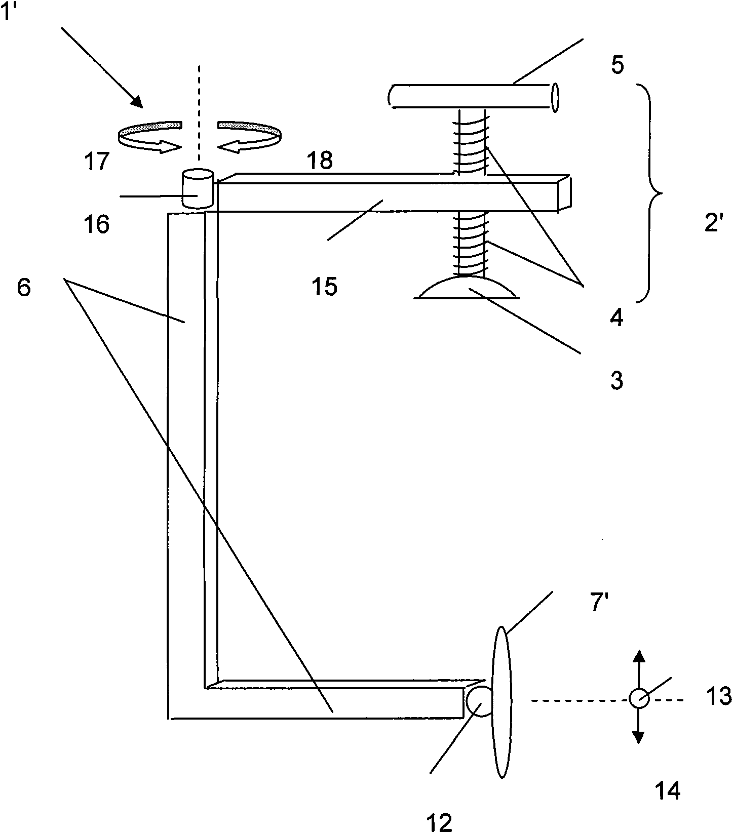
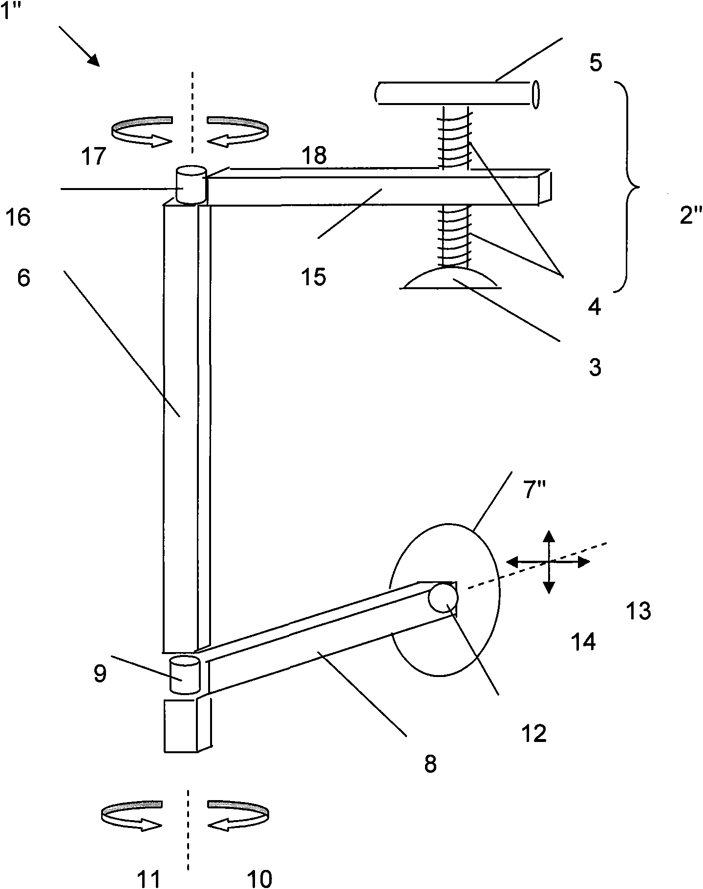
[0131] A connector, in the form of a fixture, in figure 1 Is generally represented by arrow 1.

[0132] The first joining part, in the form of a plug, in figure 1 Is generally represented by bracket 2.

[0133] The plug includes a contact pad 3 connected to the threaded shaft 4. The connection between the contact pad 3 and the threaded shaft 4 is configured to enable the contact pad 3 to be pivotally oriented relative to the threaded shaft 4.

[0134] The contact pad 3 is in the form of a solid cap with a flat bottom surface, which is similar to the conventional G-clamp contact pad known in the art. In an alternative embodiment, the contact pad 3 is a suction cup. In other embodiments, the flat bottom surface of the contact pad 3 is a releasable adhesive.

[0135] The head includes a handle 5 which is connected to the threaded shaft 4 at the end of the threaded shaft 4 away from the connection with the contact pad 3.

[0136] The spacer link 6 forms a reaction support for the clamp...


PUM


Abstract

A connector including a spacing link, and a first engagement member connected directly or indirectly to the spacing link, and a second engagement member mounted on an extension arm characterised in that the extension arm is mounted with respect to the spacing link so that the extension arm can move from one side of the spacing link to another.

Description

Technical field [0001] The invention relates to a connector. In particular, the invention relates to a device for connecting or clamping sheet materials. Background technique [0002] Angle clamps, such as the generally known "C" (also commonly referred to as "G") clamps and "F" clamps are well known in the art. Such clamps are commonly used to hold the workpieces together, for example to hold the workpieces together when forming a joint. [0003] These angle clips are named because the shape of their body resembles the letter "C" or "F". The angle clamp includes a pair of jaws connected to the main body, which are spaced apart and oriented to face each other (opposing jaws). For example, in the C clamp, one jaw is connected to the vicinity of the upper end of the "C" and is directed straight down. The second jaw is connected to the vicinity of the lower end of "C" and is oriented upward facing the other jaw. [0004] A similar setup is used on the F clamp, where the jaws are fi...

Claims


Application Information

Patent Timeline
Patent Type & Authority Applications(China)
IPC IPC(8): B25B5/00B23K37/04F16B2/02F16B2/10
CPCF16B2/02B25B5/006F16B2/10B23K37/0435B25B5/10Y10T29/49998
Inventor G·G·H·斯瓦斯布鲁克
Owner G·G·H·斯瓦斯布鲁克
Why Eureka
Try Eureka