Magnetic flowmeter output verification

A magnetic flowmeter and flow technology, applied in the direction of volume measurement, liquid/fluid solid measurement, test/calibration volume flow, etc., can solve the difficulties of magnetic flowmeter and other problems

Active Publication Date: 2010-03-31
MICRO MOTION INC
View PDF0 Cites 11 Cited by
  • Summary
  • Abstract
  • Description
  • Claims
  • Application Information

AI Technical Summary

Problems solved by technology

Determining where a magnetic flowmeter has failed can be difficult, especially when the flow tube assembly is installed in an inaccessible location
This difficulty in determining whether different parts of a magnetic flowmeter are having trouble is very challenging when the analog or pulsed output of the flowmeter itself is being interrogated

Method used


Image

  • Magnetic flowmeter output verification
  • Magnetic flowmeter output verification
  • Magnetic flowmeter output verification

Examples


Embodiment Construction

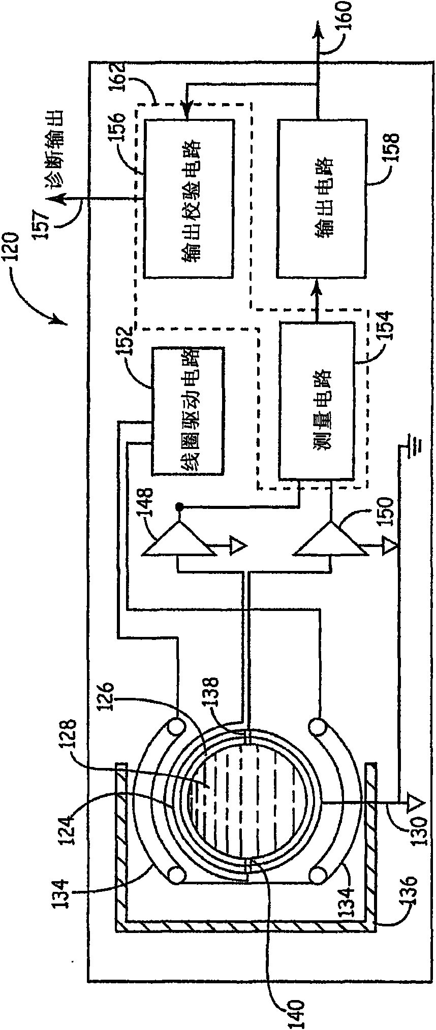
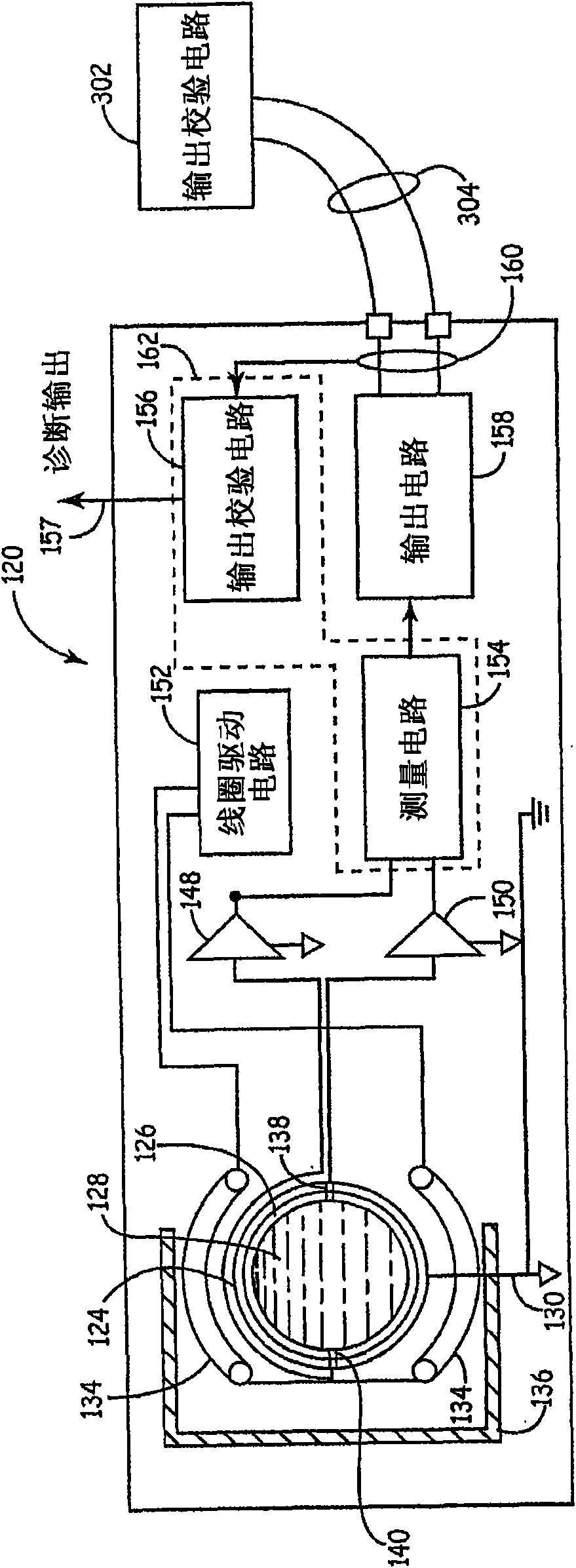
[0017] The disclosed magnetic flowmeter provides output circuit verification or diagnostics. In particular, embodiments include output verification circuitry or functionality to verify the analog or pulsed output of the magnetic flowmeter.

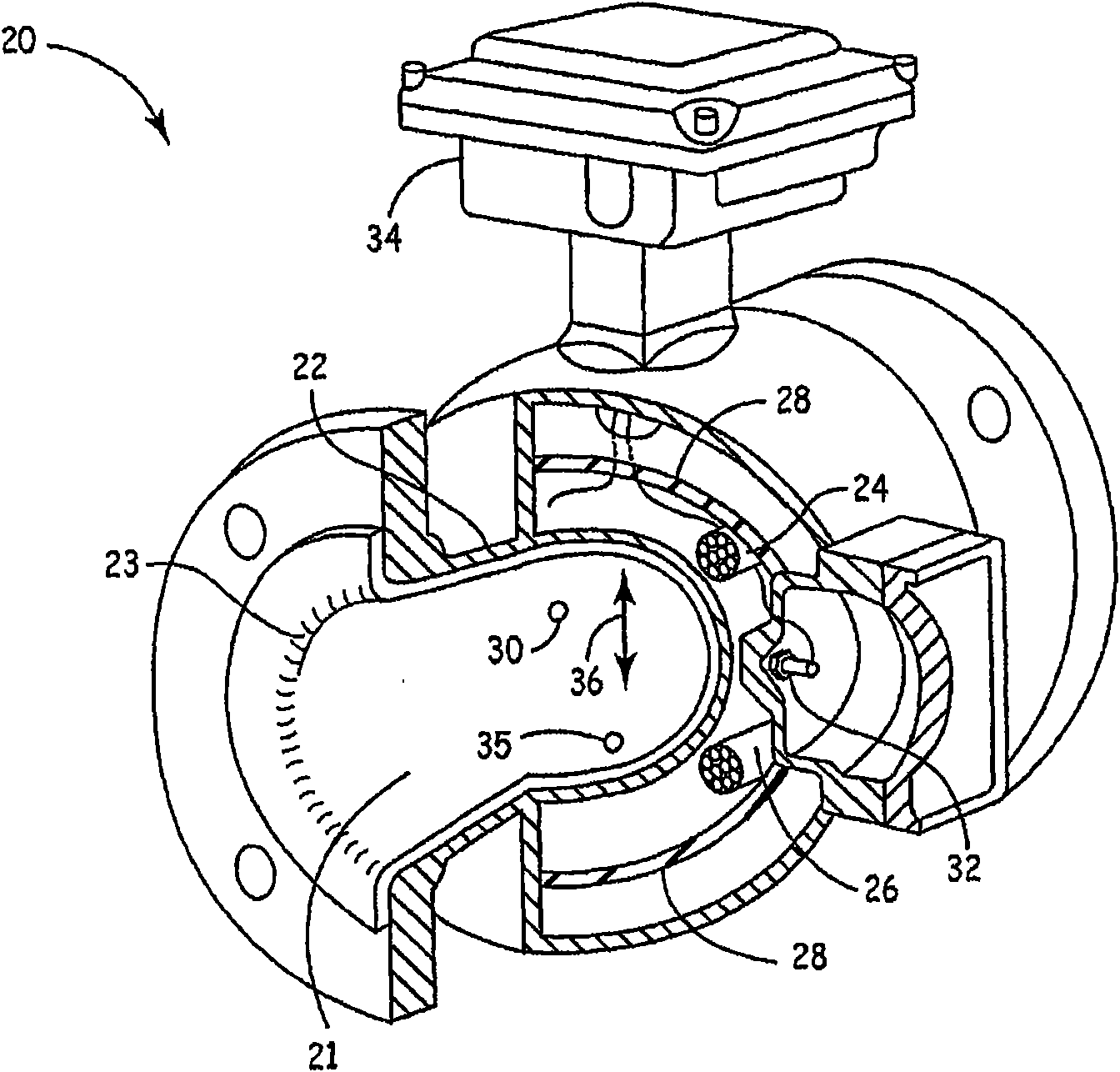
[0018] figure 1 is a partial cross-sectional view of a magnetic flow meter in which embodiments of the present invention are useful. The magnetic flowmeter 20 includes a flow tube 22 constructed of a low magnetic permeability material with an electrically insulating sleeve 23 , an electromagnet 26 composed of a coil, ferromagnetic core or shield 28 and electrodes 30 , 32 . Electromagnet 26 and electrodes 30 , 32 are wired to transmitter circuitry 34 , as is ground electrode 35 . In operation, the transmitter circuitry drives the electromagnet 26 with an electric current, and the electromagnet 26 generates a magnetic field 36 inside the flow tube 22 as indicated by the arrow. Process liquid 21 flows through the magnetic field within flow...


PUM


Abstract

A magnetic flowmeter transmitter (120) includes a flowtube (124) and measurement circuitry (154) which provides an output related to flow through the flowtube (124). Output circuitry (158), such as analog and pulse output circuitry, provides transmitter output(s) related to flow through the flowtube (124). Output verification circuitry (156) of the transmitter (120) is coupled to the output circuitry (158) and provides verification of proper operation of the output circuitry (158) by analyzing the output signals.

Description

Background technique [0001] Magnetic flowmeters are used for liquid flow measurement in fluid handling installations such as chemical plants, food processing plants, and pulp and paper mills. Magnetic flowmeters consist of a flow tube assembly that is installed in the piping system. The magnetic flowmeter also includes a transmitter connected to the flow tube assembly via a cable, or the transmitter may be integrally mounted within the flow tube assembly. [0002] Similar to other microprocessor or digital signal processor (DSP) based transmitters, magnetic flowmeters include measurement circuitry for measuring flow-related parameters of a fluid (flow rate, volume, etc.) and output circuitry , the output circuit is used to transmit flow-related output to instrumentation and control equipment. Typically, this transfer utilizes analog circuitry, such as a 4-20mA current loop, which requires an analog output circuit. In addition, flow meters typically communicate flow-related ...

Claims


Application Information

Patent Timeline
Patent Type & Authority Applications(China)
IPC IPC(8): G01F1/60G01F15/06G01F25/00G08C19/02
CPCG01F25/0007G01F1/60G01F15/063G01F15/065G01F15/068G01F25/10
Inventor R·K·舒尔兹S·R·弗斯W·G·托腾哈根K·A·亨特
Owner MICRO MOTION INC
Why Eureka
Try Eureka