Method, device and system for detecting packet loss

A packet loss detection and packet loss technology, applied in the field of communication, can solve the problem that the packet count of the entry node cannot detect the packet count, and the multi-path scenario cannot be applied.

Inactive Publication Date: 2010-04-28
GLOBAL INNOVATION AGGREGATORS LLC
View PDF0 Cites 39 Cited by
  • Summary
  • Abstract
  • Description
  • Claims
  • Application Information

AI Technical Summary

Problems solved by technology

[0006] The packet count of the ingress node cannot be counted based on the detection packets transmitted on...

Method used


Image

  • Method, device and system for detecting packet loss
  • Method, device and system for detecting packet loss
  • Method, device and system for detecting packet loss

Examples


Embodiment Construction

[0035] In order to make the purpose, technical solutions and advantages of the embodiments of the present invention clearer, the present invention will be further described in detail below in conjunction with the accompanying drawings and embodiments. It should be understood that the specific embodiments described here are only used to explain the present invention, not to limit the present invention.

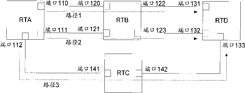
[0036] For ease of description, a specific embodiment of the present invention is introduced below. Such as figure 1 As shown, it is a schematic diagram of a network according to an embodiment of the present invention. The network includes a router RTA, a router RTB, a router RTC and a router RTD, wherein RTA is used as an entry node, RTB and RTC are used as intermediate nodes, and RTD is used as an exit node. The three ports are port 110, port 111, and port 112; the four ports on the RTB are port 120, port 121, port 122, and port 113; the two ports on the RTC are port 141 and...


PUM


Abstract

The invention relates to the field of communication, and discloses a method, a device and a system for detecting packet loss. The technical effect of detecting the situation of packet loss of each path under a multi-path scene by generating a detection message carrying multi-path identification and sequence number of the detection message through an inlet node, setting the multi-path identification as a first value, setting the sequence number of the detection message as the number of detection messages which are transmitted to the path of the detection message by the inlet node, and transmitting the detection message to the path transmitting the detection message.

Description

technical field [0001] The present invention relates to the communication field, in particular to a packet loss detection method, device and system. Background technique [0002] With the continuous development of network IPTV and video-on-demand services, network quality directly affects customer experience. Through path packet loss detection, the faulty path can be found in time, and the network manager can be notified to deal with it, which is conducive to improving the quality of network transmission. Currently, there are two implementation schemes for path packet loss detection: [0003] 1. Generate a detection message through flow triggering. Every time the ingress node generates a detection message, it will carry a message count to record the number of detection messages sent. When the intermediate node and the exit node receive the detection message, they will compare and detect The packet count and local reception count carried by the packet are used to determine w...

Claims


Application Information

Patent Timeline
IPC IPC(8): H04L12/26H04L12/56H04L47/32
Inventor 第海兵
Owner GLOBAL INNOVATION AGGREGATORS LLC
Why Eureka
Try Eureka