
Link status monitoring based on packet loss detection

a packet loss and status monitoring technology, applied in the field of data routing, can solve the problems that current internet routing protocols generally cannot route packets from an element in one private network, and are not useful on the public intern

Active Publication Date: 2019-02-05
128 TECH
View PDF102 Cites 117 Cited by
  • Summary
  • Abstract
  • Description
  • Claims
  • Application Information

AI Technical Summary

Benefits of technology

The patent describes a system where a source node sends monitoring protocol messages to a target node and receives response messages in return. By analyzing the sequences of these messages, the system can determine if there's a communication problem and determine if it's associated with the outgoing or incoming link. The target node then sends back a formatted message to the source node. This system allows for better communication between nodes and can be used with BFD messages.

Problems solved by technology

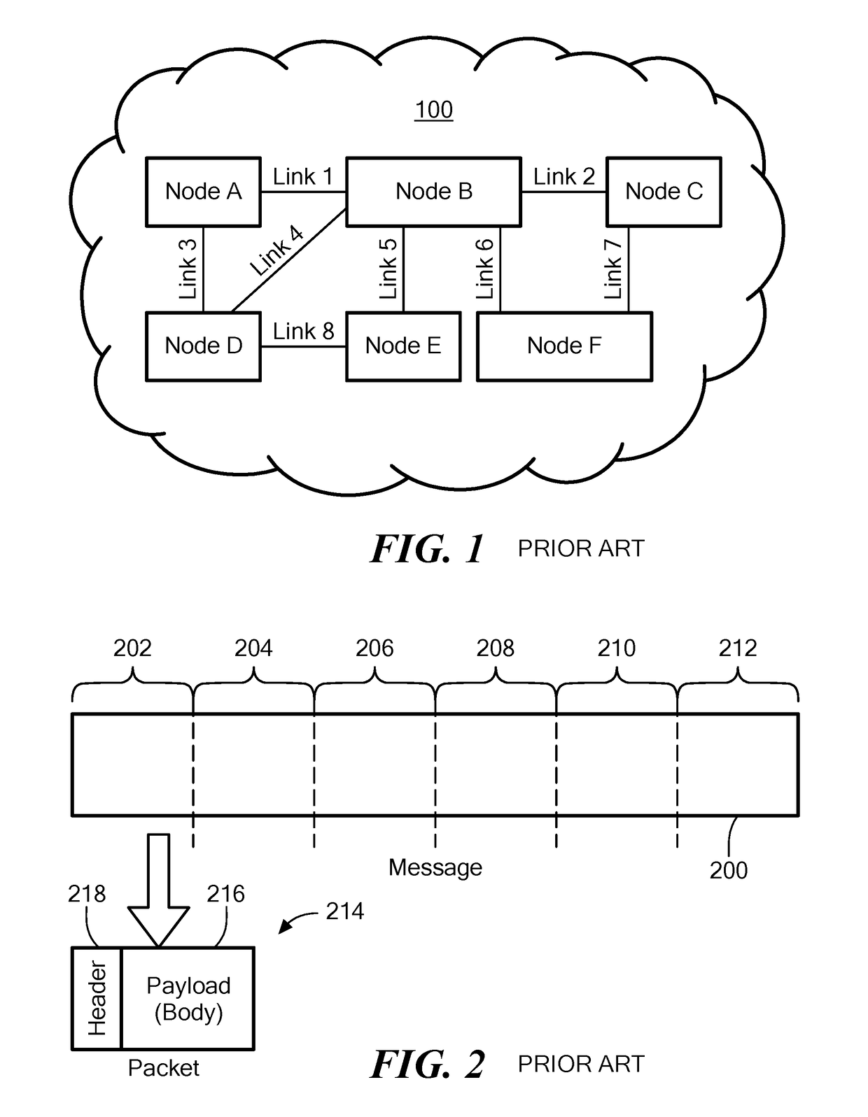
Those skilled in the art thus refer to IP as a “stateless” protocol because, among other reasons, it does not save packet path data, and does not pre-arrange transmission of packets between end points.
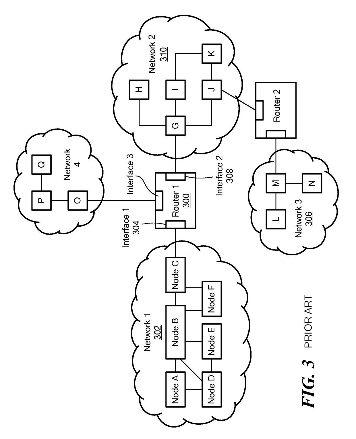
Current Internet routing protocols generally cannot route packets from an element in one private network to an element in another private network because the IP address spaces used for elements in those private networks often overlap.
These are often referred to as “unroutable” addresses, which are not useful on the public Internet.
Over the past decade, network challenges have evolved from bandwidth and broadband availability to security and mobility.

Method used


Image

  • Link status monitoring based on packet loss detection
  • Link status monitoring based on packet loss detection
  • Link status monitoring based on packet loss detection

Examples


Embodiment Construction

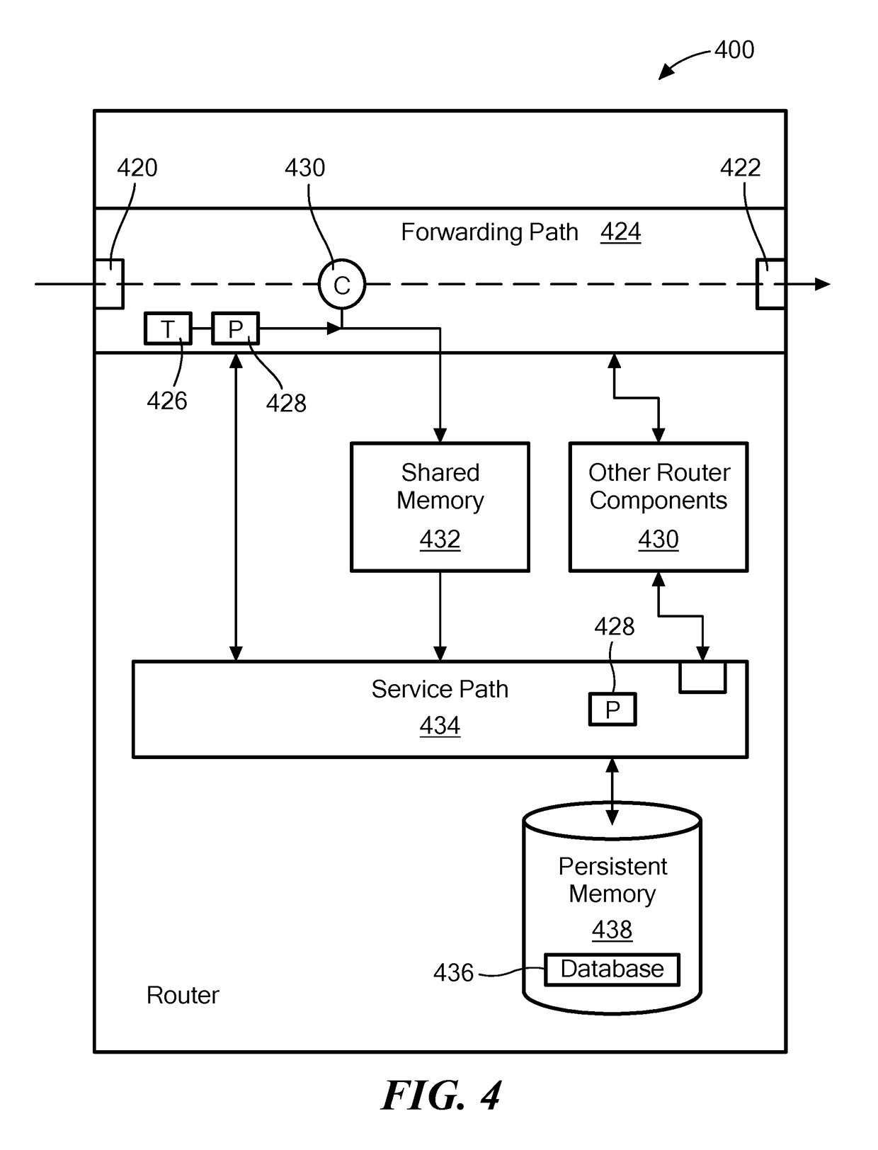
[0025]In accordance with one embodiment, a system comprises a source node and a target node. The source node is configured to transmit a series of distinct forward link monitoring protocol messages to the target node, each distinct forward link monitoring protocol message having a metadata portion including a distinct forward sequence number; receive a series of return link monitoring protocol messages from the target node, each return link monitoring protocol message responsive to a distinct forward link monitoring protocol message and having a metadata portion including a forward sequence number from the received forward link monitoring protocol message and a distinct return sequence number; determine if a communication problem occurred based on the forward and reverse sequence numbers in the series of received return link monitoring protocol messages; and when the source node determines that a communication problem occurred, determine whether the communication problem is associat...


PUM


Abstract

In exemplary embodiments of the present invention, special metadata is added to link monitoring protocol messages exchanged by pairs of adjacent nodes to allow such nodes to detect communication link failures and determine whether the failure affects an incoming communication link or an outgoing communication link. The link monitoring protocol messages may be augmented BFD messages.

Description

CROSS-REFERENCE TO RELATED APPLICATION(S)[0001]This patent application is related to U.S. patent application Ser. No. 14 / 497,954 filed Sep. 26, 2014, entitled, “NETWORK PACKET FLOW CONTROLLER,” and naming MeLampy, Baj, Kaplan, Kumar, Penfield, and Timmons as inventors, the disclosure of which is incorporated herein, in its entirety, by reference.[0002]This patent application also is related to U.S. patent application Ser. No. 14 / 562,917, filed Dec. 8, 2014, entitled, “STATEFUL LOAD BALANCING IN A STATELESS NETWORK,” and naming Timmons, Baj, Kaplan, MeLampy, Kumar, and Penfield as inventors, the disclosure of which is incorporated herein, in its entirety, by reference.[0003]This patent application also is related to U.S. patent application Ser. No. 14 / 715,036, filed May 18, 2015, entitled, “NETWORK DEVICE AND METHOD FOR PROCESSING A SESSION USING A PACKET SIGNATURE,” and naming Kumar, Timmons, and MeLampy as inventors, the disclosure of which is incorporated herein, in its entirety, ...

Claims


Application Information

Patent Timeline
Patent Type & Authority Patents(United States)
IPC IPC(8): H04L12/26H04L12/939
CPCH04L43/0829H04L49/555H04L43/10H04L43/0811H04L45/70H04L45/28H04L47/34
Inventor MENON, ABILASHPENFIELD, ROBERTKAPLAN, HADRIEL S.TIMMONS, PATRICK
Owner 128 TECH
Learn More