Cleaning structure of gas gate valve

A gate valve and gas technology, which is applied to valve devices, engine components, mechanical equipment, etc., can solve the problems of high manufacturing cost, laborious disassembly of the bottom plate, and difficult cleaning of the bottom cavity of the gas valve seat, so as to reduce the manufacturing cost and facilitate cleaning. Effect

Inactive Publication Date: 2011-09-21
江苏鑫通环保科技有限公司
View PDF0 Cites 0 Cited by
  • Summary
  • Abstract
  • Description
  • Claims
  • Application Information

AI Technical Summary

Problems solved by technology

The disadvantages of the cleaning structure of the above-mentioned gas gate valve are: the bottom cavity of the gas valve seat is not easy to clean, the disassembly of the bottom plate is very laborious, and the cleaning can only be carried out when the gate valve is opened, and the manufacturing cost is relatively high

Method used


Image

  • Cleaning structure of gas gate valve
  • Cleaning structure of gas gate valve

Examples


Embodiment Construction

[0008] The specific content of the present invention will be described in detail below with reference to the drawings and specific embodiments.

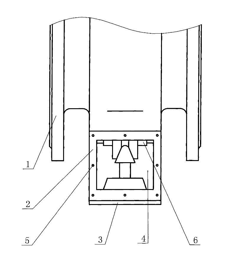
[0009] Such as figure 1 As shown, the cleaning structure of the gas gate valve includes: four side plates 2 fixedly arranged at the bottom of the valve body 1, a bottom plate 3 is fixedly arranged at the bottom of the side plate 2, and the bottom plate 3 and the side plate 2 together enclose the valve seat bottom cavity , One of the side plates 2 is provided with a cleaning port 4, and the detachable side cover is set on the side plate 2 by a number of connecting bolts to block the cleaning port 4, and the connecting bolts are matched with the mounting holes 5 provided on the side plate 2 .

[0010] Install the cleaning structure of the above structure on the gas gate valve. When it is necessary to clean the bottom cavity of the gas valve seat, use a tool to unscrew the connecting bolt from the mounting hole 5, remove the detachable side...


PUM


Abstract

The invention discloses a cleaning structure of a gas gate valve, comprising four lateral plates and a soleplate. The four lateral plates are fixedly arranged at the bottom of a valve body; the soleplate is fixedly arranged at the bottoms of the lateral plates; the soleplate and the lateral plates together surround a valve seat bottom cavity; a cleaning opening is arranged on one lateral plate and blocked by a dismountable lateral cover which is arranged on the lateral plates by a plurality of connecting bolts; and the connecting bolts are mutually matched with mounting holes which are arranged on the lateral plates. The invention has the advantages that the cleaning structure of the gas gate valve omits the assembly of the dismountable soleplate, omits corresponding gaskets, studs, nuts and corresponding processing processes, decreases the manufacture cost and can conveniently clean the interior of the gas valve seat bottom cavity under the state that the gate valve is switched off.

Description

Technical field [0001] The invention relates to a gas gate valve, in particular to a cleaning structure of the gas gate valve. Background technique [0002] Gas gate valves are used in gas transmission and distribution pipes in steel, metallurgy, coking and other industries. In actual use, because the gas contains a lot of dust and impurities often precipitate in the bottom cavity of the gas valve seat, it needs to be cleaned regularly. The cleaning structure of the existing gas gate valve is as follows: an opening and a detachable bottom plate are arranged at the bottom of the valve body, and the detachable bottom plate is in a closed state during operation. The disadvantages of the cleaning structure of the above gas gate valve are: the bottom cavity of the gas valve seat is not easy to clean, the disassembly of the bottom plate is very laborious, the cleaning can only be performed when the gate valve is open, and the manufacturing cost is relatively high. Summary of the inven...

Claims


Application Information

Patent Timeline
Patent Type & Authority Patents(China)
IPC IPC(8): F16K43/00
Inventor 杨昌华马爱华
Owner 江苏鑫通环保科技有限公司
Why Eureka
Try Eureka