Vertical engraving and milling machine spindle motor installation structure

A spindle motor and installation structure technology, which is applied in the field of machine tools, can solve the problems of long debugging and calibration time, low efficiency, and failure to meet customers' high-precision production requirements, and achieve the effect of improving debugging efficiency and reducing debugging and calibration time

Active Publication Date: 2017-10-31
陈美青
View PDF10 Cites 0 Cited by
  • Summary
  • Abstract
  • Description
  • Claims
  • Application Information

AI Technical Summary

Problems solved by technology

Although the installation structure of the spindle motor of the vertical engraving and milling machine can realize the fixed spindle motor, there are many shortcomings; if the spindle motor needs to be installed in multiple channels, it is difficult to ensure that the accuracy of all the spindle motors is consistent; multiple spindle motors are debugged and corrected one by one , the required debugging and correction time is long, and the efficiency is low, which cannot meet the high-precision production requirements of some customers

Method used


Image

  • Vertical engraving and milling machine spindle motor installation structure
  • Vertical engraving and milling machine spindle motor installation structure
  • Vertical engraving and milling machine spindle motor installation structure

Examples


Embodiment 1

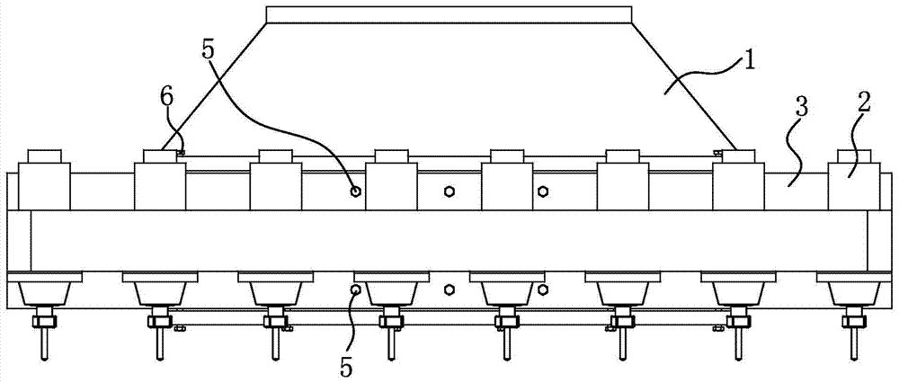
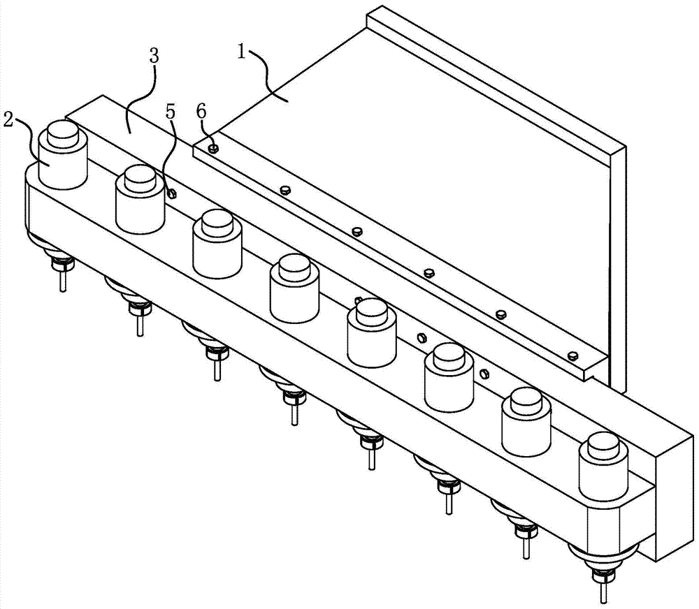
[0024] Such as Figure 1 to Figure 3 As shown, the vertical engraving and milling machine includes a machine head 1 and a plurality of spindle motors 2, and the number of spindle motors 2 given in the accompanying drawings is eight.

[0025] Such as Figure 1 to Figure 6 As shown, the spindle motor installation structure of the vertical engraving and milling machine includes a bar-shaped beam 3, the spindle motor 2 is fixed on the beam 3, and the beam 3 is fixed on the machine head 1.

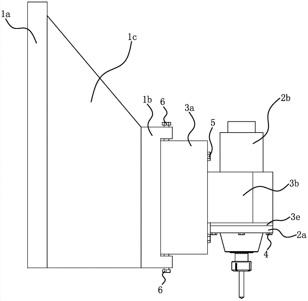
[0026] Specifically, as Figure 6 As shown, the beam 3 includes a strip-shaped bottom beam portion 3a and a strip-shaped motor seat portion 3b protruding from the bottom beam portion 3a. The cross section of the bottom beam part 3a is rectangular; it is convenient for the cross beam 3 to be connected with the machine head 1, and the bottom beam part 3a is provided with a bolt hole 3c. Eight motor installation holes 3d are distributed at equal intervals along the longitudinal direction of the...

Embodiment 2

[0031] The structure and principle of this embodiment are basically the same as that of Embodiment 1, and the basic similarities will not be redundantly described, and only the differences will be described, and the differences are as follows: Figure 7 As shown, metal strips 7 are placed between the adjusting bolt 6 and the top and bottom surfaces of the beam 3 .

Embodiment 3

[0033]The structure and principle of this embodiment are basically the same as that of Embodiment 1, and the basic similarities will not be redundantly described, and only the differences will be described, and the differences are as follows: Figure 8 As shown, the bolt level adjustment mechanism includes a second installation groove 3f provided on the rear side of the bottom beam portion 3a of the crossbeam 3, and multiple pieces of the adjustment bolts are screwed on the upper side wall and the lower side wall of the second installation groove 3f. The bolt 6 , the crossbeam mounting plate 1b of the machine head 1 is embedded in the second mounting groove 3f, and the adjusting bolt 6 abuts against the top surface and the bottom surface of the crossbeam mounting plate 1b.


PUM


Abstract

The invention provides a spindle motor installation structure of a vertical type carves-milling machine, belonging to the technical field of machine tools, for solving the problem that in the existing spindle motor mounting structures, the precision of all spindle motors can not be guaranteed easily. The spindle motor installation structure of the vertical type carves-milling machine comprises a strip-shaped cross beam, wherein motor mounting holes with the quantity equal to that of the spindle motors are formed in the cross beam, the spindle motors and the motor mounting holes are arranged in a one-to-one correspondence manner, the spindle motors are fixed in the motor mounting holes in the cross beam, the cross beam is fixed on the front side surface of a machine head through first fastening bolts, and adjusting bolts and a bolt horizontal adjustment mechanism capable of adjusting the horizontal state of the cross beam by rotating and screwing the adjusting bolts are arranged between the machine head and the cross beam. In the spindle motor installation structure, during the machining process of the cross beam, by controlling the machining precision, the requirements on parameters including the perpendicularity of the motor mounting holes, the center-to-center distances among the motor mounting holes, the parallelism among the motor mounting holes, and the like, are guaranteed, therefore, the consistency of the precision of all the spindle motors is significantly improved, and further, the machining precision of the carves-milling machine is greatly improved.

Description

technical field [0001] The invention belongs to the technical field of machine tools, and relates to a vertical engraving and milling machine, in particular to a vertical engraving and milling machine spindle motor installation structure. Background technique [0002] Some products in bathroom hardware, kitchen hardware, door handles are made of copper, such as Figure 5 Faucet body shown. In the traditional processing method of the faucet, the main body blank is sequentially subjected to rough polishing, fine polishing, fine polishing and electroplating. The scraped copper on the surface of the billet is doped with impurities such as sand grains, so there are problems such as difficult separation and purification of copper and waste of resources. [0003] For this reason, the applicant has proposed a horizontal high-efficiency engraving and milling machine (application publication number: CN104070904A) and a vertical engraving and milling machine (authorized announcement n...

Claims


Application Information

Patent Timeline
Patent Type & Authority Patents(China)
IPC IPC(8): B23Q1/01B23Q5/10
CPCB23Q1/0063B23Q1/015B23Q5/10
Inventor 陈美青
Owner 陈美青
Why Eureka
Try Eureka