Automatic shot blasting steel shot recovering device in steel pipe

A technology of automatic recovery and steel pipe, applied in the processing device of used abrasive, abrasive, metal processing equipment, etc., can solve the problems of equipment, cost, power consumption increase, purging device, labor and energy consumption, etc. Achieve the effect of saving energy and manpower, reliable structure principle, convenient installation and use

Inactive Publication Date: 2010-06-02
张景远
View PDF0 Cites 25 Cited by
  • Summary
  • Abstract
  • Description
  • Claims
  • Application Information

AI Technical Summary

Problems solved by technology

[0002] At present, the derusting technology for the inner and outer walls of steel pipes generally adopts the method of sand blasting, which is completed by a shot blasting derusting machine. , there is the problem of recycling steel grit. In the past, steel grit was recovered by covering the end of the steel pipe with a high-power vacuum cleaner to suck out the dust and steel grit flying up in the pipe after derusting, and send it back after separation. to the inner conveyor belt for the throwing head; the disadvantage of this method is that it needs a strong suction force to suck the flying steel sand out of the pipe, and its equipment, cost and power consumption will increase; The steel sand in the steel pipe is due to the gravity of the steel sand, and the dust suction device cannot suck the steel sand that falls on the inner wall of the steel pipe out of the pipe. It is necessary to increase the blowing device to complete the cleaning of the remaining sand in the pipe; the third is to use the steel pipe to stand up method, will greatly increase the cost of cleaning
In addition, the problem existing in the prior art is that the steel grit shot out by the throwing head and the steel rust knocked down from the inner wall of the steel pipe are not cleaned in time and accumulate in the steel pipe. When cleaning, a large-power cyclone dust collector is required to extract the steel grit out of the pipe. Because the pipeline is generally longer than 12 meters, the suction of the cyclone can only suck out the steel sand and steel rust at a depth of 7 or 8 meters behind the pipeline. The front three or four meters must be blown outward by installing a high-pressure fan, which is laborious and expensive. energy consumption, high cost

Method used


Image

  • Automatic shot blasting steel shot recovering device in steel pipe
  • Automatic shot blasting steel shot recovering device in steel pipe
  • Automatic shot blasting steel shot recovering device in steel pipe

Examples


Embodiment

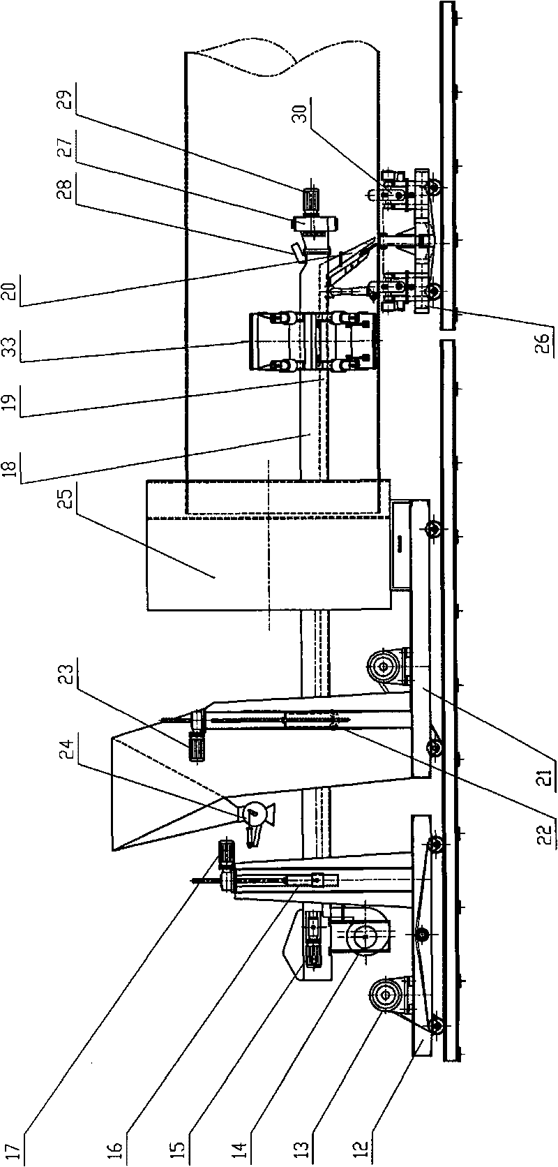
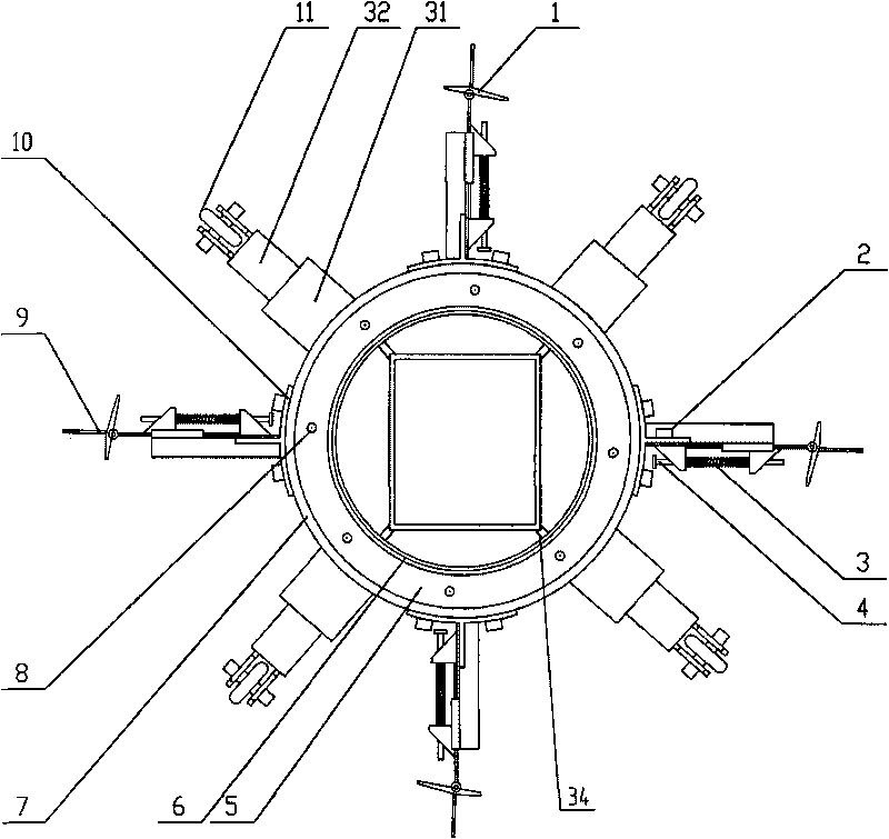
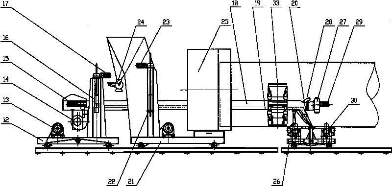
[0014] The main structure of this embodiment includes a front movable plate 1, a rear fixed plate 2, a spring 3, a spring column 4, a runner gland 5, a runner inner ring 6, a runner outer ring 7, a bearing 8, a polyurethane rubber strip 9, Sand scraper base 10, walking wheel 11, throwing head trolley 12, walking reducer 13, high pressure fan 14, conveyor belt deceleration motor 15, throwing head rod lifting device 16, conveyor belt reducer 17, throwing head rod 18, fan transmission Air pipe 19, front guide air nozzle 20, opposite pipe car 21, roller device 22, lifting motor 23, sand output controller 24, workpiece pair tube 25, transmission car 26, direct-connected throwing head 27, conveyor belt 28, throwing head Motor 29, driving wheel 30, axle sleeve 31, vertical shaft 32 derusting sand reclaimer 33 and steel plate 34; Runner outer ring 7 is two, and structure is its outside and a side drilling of a ring, respectively with scraping sand plate The drilling hole of the base 1...


PUM


Abstract

The invention belongs to the technical field of metal rust removal processing, and relates to an automatic shot blasting steel shot recovering device in a steel pipe. The primary structure of the device comprises a front active plate, a rear fixing plate, a runner gland, a runner inner ring, a runner outer ring, a sandplow base, a traveling wheel, a blast wheel trolley, a high pressure fan, a blast wheel rod, a fan gas pipe, an alignment vehicle, a roller device, a sanding controller, a workpiece alignment tube, a transmission vehicle, a direct blast wheel, a conveyor belt and the like. All parts are processed and assembled into the integral steel shot recovering device based on the structural principle of the conventional sand throwing mechanism; and the integral steel shot recovering device is divided into a striking-off unit, a runner unit and a traveling unit according to the functions. The steel shot and a rust dust shipping mechanism consists of the blast wheel trolley, the alignment vehicle and the transmission vehicle. The steel shot recovering device has the advantages of reliable principle, convenient use and installation, high recovery rate, low cost, which is used for removing rust of the inner wall of the various steel pipes.

Description

Technical field: [0001] The invention belongs to the technical field of metal derusting processing, and relates to an automatic recovery device for shot blasting and derusting steel sand in steel pipes. Background technique: [0002] At present, the derusting technology for the inner and outer walls of steel pipes generally adopts the method of sand blasting, which is completed by a shot blasting derusting machine. , there is the problem of recycling steel grit. In the past, steel grit was recovered by covering the end of the steel pipe with a high-power vacuum cleaner to suck out the dust and steel grit flying up in the pipe after derusting, and send it back after separation. to the inner conveyor belt for the throwing head; the disadvantage of this method is that it needs a strong suction force to suck the flying steel sand out of the pipe, and its equipment, cost and power consumption will increase; The steel sand in the steel pipe is due to the gravity of the steel sand...

Claims


Application Information

Patent Timeline
Patent Type & Authority Applications(China)
IPC IPC(8): B24C9/00
Inventor 张景远张聚成
Owner 张景远
Why Eureka
Try Eureka