Ball screw rod device

A ball screw and ball nut technology, used in bearings, linear motion bearings, shafts and bearings, etc., can solve the problems of stroke limitation, shortening, and 12 stroke compression of the ball nut, and achieve the effect of avoiding stroke limitation.

Active Publication Date: 2012-02-29
TBI MOTION TECH CO LTD
View PDF0 Cites 0 Cited by
  • Summary
  • Abstract
  • Description
  • Claims
  • Application Information

AI Technical Summary

Problems solved by technology

[0005] However, the known lubricating units 13 are located on both sides of the ball nut 12, and the total volume of these lubricating units 13 is approximately similar to the ball nut 12, so the stroke of the ball nut 12 will be compressed and shortened.
In this way, the stroke limit of the application of the ball screw device 1 is also caused.

Method used


Image

  • Ball screw rod device
  • Ball screw rod device
  • Ball screw rod device

Examples


no. 1 example

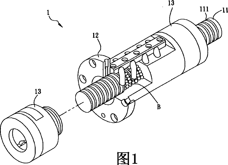
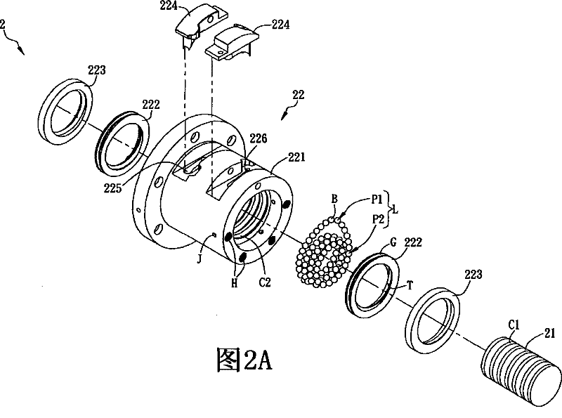
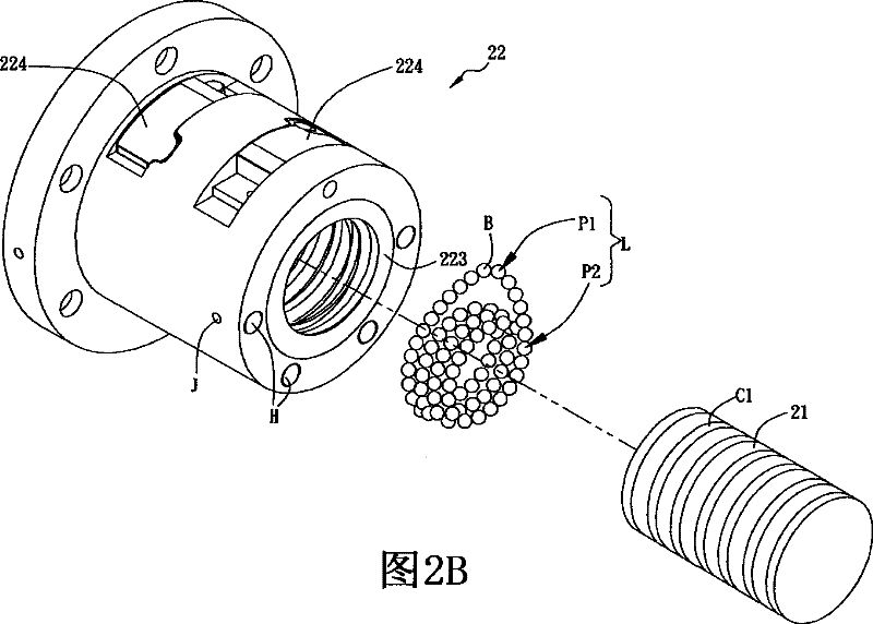
[0039] Please refer to Figure 2A and Figure 2B shown, where Figure 2A It is an exploded schematic view of the ball screw device 2 of this embodiment, Figure 2B It is a combined schematic diagram of the ball screw device 2 . The ball screw device 2 of the first embodiment of the present invention includes a screw 21 and a ball nut 22 .

[0040] The screw 21 has a thread groove C1. The ball nut 22 is sheathed and slidably disposed on the screw rod 21 , and has a nut body 221 and a lubricating element 222 . In this embodiment, the screw 21 has two lubricating elements 222 as an example for illustration, but it is not limiting.

[0041] The nut body 221 has a thread groove C2, and these thread grooves C1, C2 correspond to form a first ball channel P1. The ball nut 22 is provided with a second ball channel P2, the first ball channel P1 and the second ball channel P2 together form a circulation path L, and a plurality of balls B move in the circulation path L. In addition...

no. 2 example

[0049] Please refer to Figure 4A and Figure 4B shown, where Figure 4A It is an exploded schematic diagram of the ball screw device 3 of this embodiment, Figure 4BIt is a combined schematic diagram of the ball screw device 3 . The difference between the ball screw device 3 and the first embodiment is that the ball nut 32 has a nut body 321, a lubricating element 322 and a limiting element 323, and the lubricating element 322 and the limiting element 323 are arranged at one end of the nut body 321, and The lubricating element 322 is sandwiched between the limiting element 323 and the nut body 321 . In this embodiment, two lubricating elements 322 and two limiting elements 323 are used for illustration, and are respectively disposed at two ends of the nut body 321 .

[0050] In addition, in this embodiment, the limiting element 323 further has at least one through hole H, through which fluid such as lubricating oil can be injected into the lubricating element 322 . Herei...


PUM


Abstract

The invention discloses a ball screw rod device, comprising a screw rod and a ball screw cap. The ball screw cap is sleeved on the screw rod in a sliding manner, and provided with a screw cap body and a lubricant element. The lubricant element is arranged between the screw cap body and the screw rod, and the lubricant element is respectively contacted with the screw rod and the screw cap body. Inthe ball screw rod device, the lubricant element is arranged between the nut body and the screw rod, such that the ball screw cap and the screw rod have a lubricant function. Because the lubricant element is internally arranged in the ball screw cap, the stroke of the ball screw cap can not be compressed and shortened due to the lubricant element so as to further avoid the limitation of the stroke when the ball screw rod device is applied.

Description

technical field [0001] The invention relates to a ball screw device, in particular to a ball screw device in which a lubricating element is arranged between a nut body and a screw rod. The device has a lubricating function and does not compress the stroke of the ball nut. Background technique [0002] In various linear transmission systems, the rotation is converted into linear transmission through the cooperation of the screw and the nut of the ball screw device. In addition, the cyclically acting balls and the ball nut and the screw rod are matched with each other to reduce the friction between the ball nut and the screw rod, so that the linear transmission system runs more smoothly. [0003] Please refer to figure 1 As shown, a known ball screw device 1 includes a screw 11 , a ball nut 12 and two lubricating units 13 . The ball nut 12 is sheathed and slidably disposed on the screw rod 11 , and the lubricating units 13 are sleeved on the screw rod 11 and located on two s...

Claims


Application Information

Patent Timeline
Patent Type & Authority Patents(China)
IPC IPC(8): F16C29/06
Inventor 李进胜杨进财
Owner TBI MOTION TECH CO LTD
Why Eureka
Try Eureka