Telescopic guide rail

A telescopic and guide rail technology, which is applied to furniture parts, household utensils, drawers, etc., can solve the problems of unfavorable bearing capacity of telescopic guide rails, and achieve the effect of uncomplicated structure

Inactive Publication Date: 2010-06-02
PAUL HETTICH
View PDF0 Cites 1 Cited by
  • Summary
  • Abstract
  • Description
  • Claims
  • Application Information

AI Technical Summary

Problems solved by technology

This has a negative effect on the load-carrying capacity of the telescopic guide rail, in particular if part of the running ...

Method used


Image

  • Telescopic guide rail
  • Telescopic guide rail
  • Telescopic guide rail

Examples


Embodiment Construction

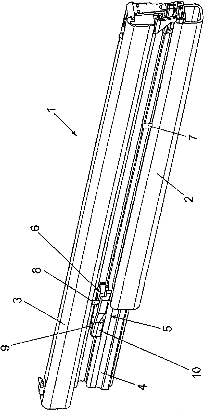
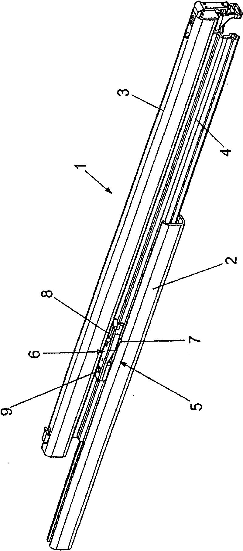
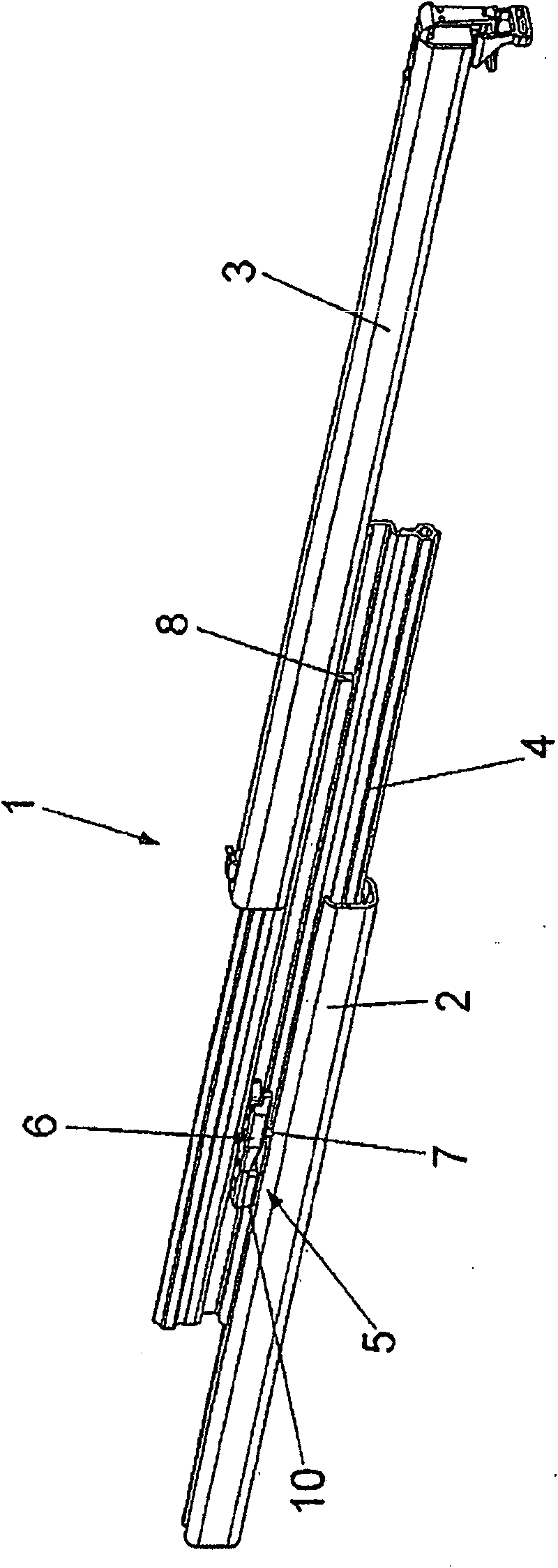
[0027] exist Figures 1 to 3 The telescopic guide rail shown in full is denoted by reference numeral 1, which includes a main body rail 2 that can be fixed on the main body side, a running rail 3 that can be connected to a pull-out member such as a drawer, and a set on the main body rail. 2 and the intermediate rail 4 extending the pull-out length between the running rail 3.

[0028] In addition, the telescopic guide rail 1 is also provided with a process control device 5, which ensures that only when the middle rail 4 is pulled out to the maximum relative to the main rail 2 adjacent to it, the running rail 3 can be moved relative to the The middle rail 4 is moved, and the process control device 5 can also ensure that the middle rail 4 can only move back from its fully pulled-out position when the running rail 3 moves back to the maximum relative to the middle rail 4 in the direction of insertion. back to the closed position.

[0029] Such a process control device 5 is desir...


PUM


Abstract

Disclosed is a telescopic guide rail (1) for extractable furniture parts such as drawers or the like, comprising a body rail (2) that can be mounted on a furniture part, a drawer rail (3) that can be connected to an extractable furniture part, a central rail (4) which is disposed between the body rail (2) and the drawer rail (3) and increases the pull-out length, and a control appliance (5) by means of which the drawer rail (3) is coupled to the central rail (4) during pull-out from the closing position until the central rail (4) is deployed to the maximum pulled-out position and is blocked in said position with respect to the body rail (4) while the drawer rail (3) is simultaneously decoupled from the central rail (4), the central rail (4) being displaced in the closing direction with respect to the body rail (2) only when the drawer rail (3) is maximally displaced in the direction of insertion in relation to the initially blocked central rail (4), thereby being coupled again to the central rail (4). The control appliance (5) is composed of a coupling member (6), which is provided with two sliding guides (6a, 6b) extending in an mirror-inverted manner to one another, a first slide (7) fixed to the body rail (2) and associated to a first sliding guide (6a), and a second slide (8) fixed to the drawer rail (3) and associated to the second sliding guide (6b), wherein the coupling member (6) is pivotably mounted about an axis (9) that extends perpendicular to the plane of displacement of the telescopic guide rail (1) and the sliding guides (6a, 6b) extend in a V-shape by expanding one in relation to the other in such a manner that during the entry of the first slide (7) into the first sliding guide (6a) associated therewith a switching of the coupling member (6) and thus a release of the second slide (8) from the second sliding guide (6b) associated therewith is caused and vice versa.

Description

technical field [0001] The invention relates to a telescopic guide rail for a furniture pull-out piece, such as a drawer, which comprises a main body rail that can be fixed on the furniture main body, a running rail that can be connected with the furniture pull-out piece, and the main body rail and the running rail Between, the middle rail that prolongs the extension length and a process control device, by means of which the running rail is always coupled with the middle rail when it is moved out of the closed position until the middle rail has reached its maximum extension position, And in this position, the intermediate rail is locked relative to the main rail when the running rail is decoupled from the intermediate rail at the same time, and when the running rail is moved to the maximum in the direction of insertion relative to the first locked intermediate rail and at this time reconnects with the intermediate rail Only when coupling is the intermediate rail able to move a...

Claims


Application Information

Patent Timeline
IPC IPC(8): A47B88/10A47B88/493
CPCA47B2210/0081A47B88/10A47B2210/007A47B88/443A47B88/493A47B2210/0064
Inventor R·布林克曼
Owner PAUL HETTICH
Why Eureka
Try Eureka