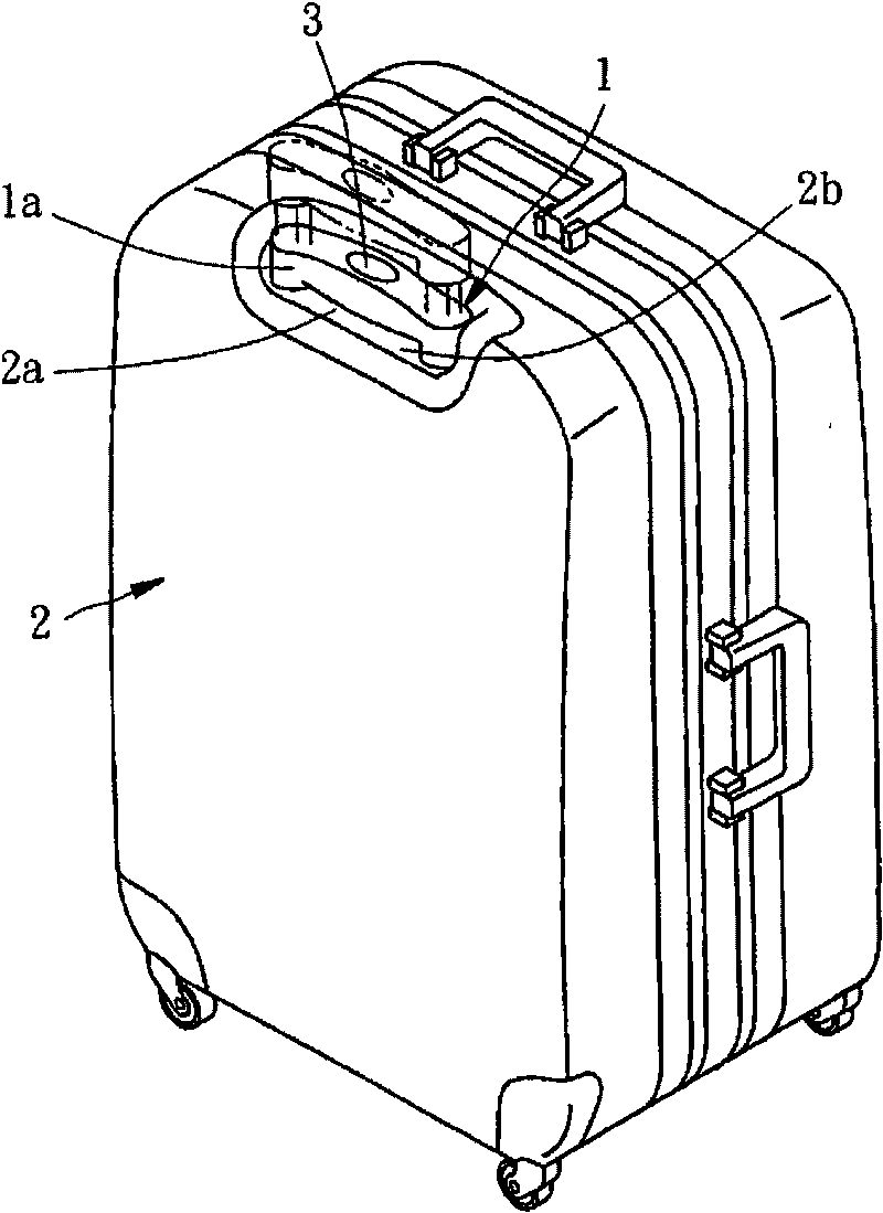
[0036] The present invention is used for the protective structure of the pull rod of the luggage case with the function of bouncing up. The pull rod is used as a suitcase controlled by the button as the bouncing up control. The spring of the pop-up structure pushes the pull rod to make it bounce up to a predetermined height, and it is convenient for the user to hold the handle on the top of the pull rod so as to pull out the pull rod for use. This will not go into details, what is relevant to the present invention is the button, hereby narrate the relationship between the button and the pull bar protective structure of the present invention as follows:
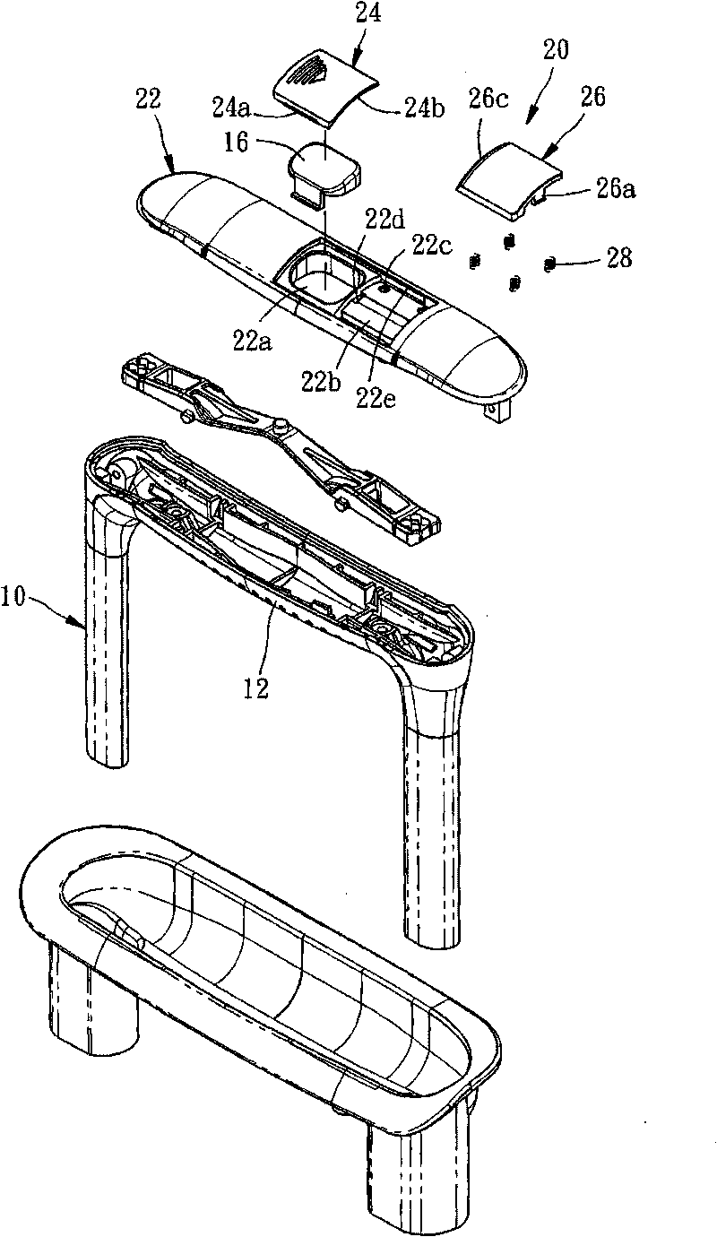
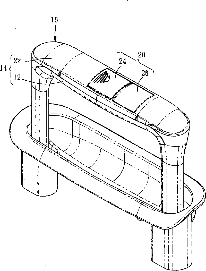
[0037] Figure 2 to Figure 4 Shown is a protective structure for a luggage trolley with a pop-up function according to a preferred embodiment of the present invention. The trolley protective structure 20 has the function of preventing the trolley 10 from automatically bouncing up without warning when it is not controlled. It includes a Bearing seat 22, a sliding cover 24, a decorative plate 26 and four elastic parts that are respectively springs 28, wherein:
[0038] The seat 22 is a plate-shaped body, and is combined with a base 12 to form a handle 14 for the pull rod 10 to be held by the user's hand, and a part of the spring-up structure is provided between the seat 22 and the base 12; The middle position of the seat 22 of the example is provided with a through hole 22a, the hole 22a provides the button 16 for releasing the clamping relationship between the pop-up structure and the pull rod to be movably accommodated therein, and the side adjacent to the hole 22a is recessed to form a Chamber 22b, the bottom surface of the chamber 22b has four countersunk holes 22c that do not penetrate, each counterbore 22c is located at each corner of the chamber 22b, and two positioning holes 22d run through the chamber 22b, and two long chute 22e parallel The two long sliding grooves 22e are arranged on both sides of the through hole 22a and the chamber 22b, and together constitute a sliding rail for the sliding cover 24 to slide.
[0039] please cooperate Figure 5 , Image 6 As shown, the sliding cover 24 is an arc-shaped plate, and has a guide block 24a on both sides to cooperate with the corresponding long chute 22e respectively, and the sliding cover 24 combined with the seat 22 can slide along the The path provided by the rail is at Figure 4 A masked position P1 is shown with Figure 9 Switching positions between an unshielded position P2 shown, the sliding cover 24 also has a first inclined surface 24b at the front edge.
[0040] please cooperate Figure 7 As shown, the decorative plate 26 is also an arc-shaped plate, and has two hook pieces 26a extending downward from opposite side edges respectively, and a hook portion 26b is formed at the end of each hook piece 26a. The decorative plate 26 is formed by the The two hook pieces 26a pass through the corresponding positioning holes 22d to combine with the seat 22, and the hook portion 26b at the end of the hook piece 26a touches the bottom surface of the seat 22 to prevent the relative seat 22 from getting loose. In addition, the decoration The plate 26 has a second inclined surface 26c on the side edge provided with one of the hook pieces 26a to cooperate with the first inclined surface 24b of the sliding cover 24. Longitudinal to Figure 4 A first position S1 shown with Figure 9 A second position S2 is shown moving up and down.
[0041] The four springs 28 are arranged between the seat 22 and the decorative plate 26. One end of each spring 28 is pressed against the counterbore 22c, and the other end is pushed against the bottom surface of the decorative plate 26. The springs 28 provide an upward thrust to promote the decorative plate. 26 is constantly moving towards the first position S1.
[0042] The above is the description of the pull rod protection structure 20 of a preferred embodiment of the present invention, and its operation and achievable effect are explained as follows:
[0043] exist Figure 3 to Figure 5In the state shown, the slide cover 24 is at the shielding position P1, and the button 16 is hidden below so that it cannot be exposed. The limitation of the sliding cover 24 can restrain the decoupling situation between the pop-up structure and the pull rod 10 when the luggage case is bumped by external force, and has the disadvantage of preventing the pull rod 10 from bouncing up automatically without warning. At the same time, the decorative plate 26 stops at the first position S1 due to being pushed by the springs 28, and the end hook portion 26b of the hook piece 26a abuts against the bottom surface of the seat 22, and is positioned at the shielding position P1. The sliding covers 24 are arranged adjacent to each other, so as to maintain the integrity of the appearance of the handle 14 and have a beautifying effect.
[0044] When the user wants to use the automatic lift function of the pull rod 10 in order to hold the handle 14, we only need to push the sliding cover 24 toward the decorative plate 26 with fingers, and use the first inclined surface 24b of the sliding cover 24 to guide the decorative plate 26. The second slope 26c can press down the decorative panel 26, as Figure 8 As shown, until the sliding cover 24 slides into the chamber 22b of the socket 22 and the decorative plate 26 descends to the second position S2, at this time the sliding cover 24 is constantly pushed by the spring 28 to the first position S1 due to the decorative plate 26 will be steadily and reliably limited to Figure 9 The shown unshielded position P2 also causes the button 16 to be exposed and can be pressed smoothly by us, so that the control pull rod 10 automatically bounces up to hold the handle 14 for us. On the contrary, only need push slide cover 24 with reverse direction again, can reply as image 3 status.
[0045] In the above embodiment, the decorative plate 26 is mainly used to maintain the integrity of the appearance of the handle 14, and is used with the spring 28 to resist the sliding cover 24 to limit it to the unshielded position P2. However, it must be noted that to achieve the present invention The target structure does not necessarily have to have the decorative plate 26 and the spring 28. In other words, the sliding cover 24 can be switched and moved directly above the perforation 22a or the chamber 22b to achieve the purpose of covering the button 16 or not. Under this structure, In consideration of its aesthetics, the chamber 22b can be made into a non-open type for hiding and storing the sliding cover 24 at the unshielded position P2.
[0046] The above descriptions are only preferred feasible embodiments of the present invention, and all equivalent structural changes made by applying the specification and claims of the present invention should be included in the patent scope of the present invention.