Reciprocating compressor

A compressor and reciprocating technology, applied in the direction of liquid variable displacement machinery, mechanical equipment, machines/engines, etc.

Inactive Publication Date: 2010-06-09
HOERBIGER KOMPRESSORTECHNIK HLDG GMBH
View PDF9 Cites 20 Cited by
  • Summary
  • Abstract
  • Description
  • Claims
  • Application Information

AI Technical Summary

Problems solved by technology

However, due to the relatively high compressibility of the compressed actuation gas, it is necessary to precisely determine the amount of switching gas and precisely set the actuation time

Method used


Image

  • Reciprocating compressor
  • Reciprocating compressor
  • Reciprocating compressor

Examples


Embodiment Construction

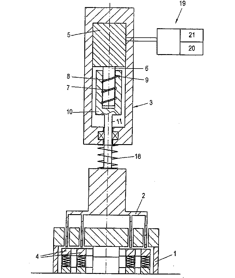
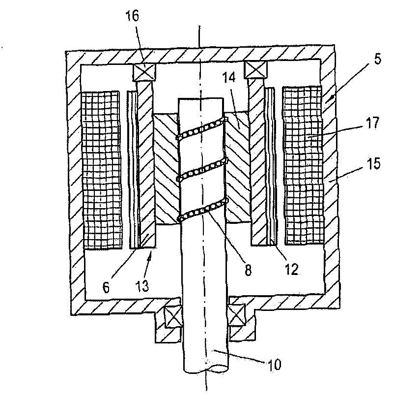
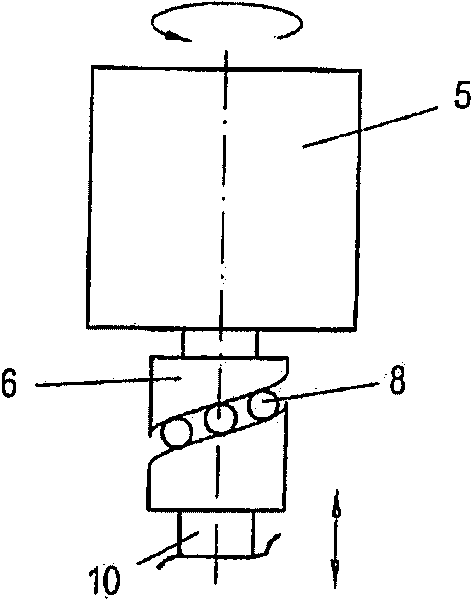
[0019] according to figure 1 , a reciprocating compressor (not further shown in more detail) comprising a valve unloader 2 provided on an automatically acting suction valve 1 of the compressor, said valve unloader being electrically controlled during a controllable phase of the compressor cycle The means 3 are actuated to keep the two annular sealing elements 4 of the suction valve 1 open. To this end, the actuating device 3 comprises an electric motor 5 as drive means, the driven element 6 of which (shown here as a central shaft) comprises a low-friction rolling element 8 extending obliquely in the direction of rotation. The guide surface 7 (shown here as a helical groove on the peripheral surface), the low-friction rolling element 8 on the other hand interacts with a corresponding guide surface 9 extending in an oblique manner on the non-rotating lifting element 10, said non-rotating A rotating lifting element 10 is connected to the valve unloader 2 .

[0020] As long as t...


PUM


Abstract

The present invention discloses a reciprocating compressor which is provided with an output speed controller, wherein, an actuator (3) which is used for causing a valve unloader (2) on a suction valve (1) to keep open comprises an electric motor (5) used as a driving device. A driven component (6) of the electric motor (5), a nonrotatable lifting component (10) of the valve unloader (2) and a rolling component (8) provided therebetween are combined to a roller screw driver. Thus the actuator (3) which has the advantages of smaller dimension, capacity for precisely adjusting, higher actuating force and higher dynamic moving performance is realized.

Description

technical field [0001] The invention relates to a reciprocating compressor with a capacity control device, comprising a valve unloader installed at at least one automatically acting suction valve of the compressor, said valve unloader being part of the compressor's working cycle It also relates to a method of controlling the capacity of such a reciprocating compressor by keeping at least one sealing element of a suction valve in an open state by means of an electric actuating device. Background technique [0002] To control the capacity of reciprocating compressors, which preferably operate at constant rotational speed, so-called reverse flow control is usually employed, in which at least one suction valve per cylinder is kept open over a certain range of the compression stroke. The pulling force exerted by the gas pressed back through the suction valve which is kept open will close the sealing element of the corresponding suction valve after overcoming a part of the piston ...

Claims


Application Information

Patent Timeline
Patent Type & Authority Applications(China)
IPC IPC(8): F04B39/00F04B49/06
CPCF04B49/243F04B39/00F04B35/04F04B17/04
Inventor B·施皮格尔P·施泰因吕克
Owner HOERBIGER KOMPRESSORTECHNIK HLDG GMBH
Why Eureka
Try Eureka