
Rugged MEMS Switches

A micro-electromechanical switch, micro-electromechanical technology, applied in circuits, relays, electrical components, etc., can solve problems such as performance degradation and fixation, accelerated contact area wear, failure, etc., to achieve the effect of good stability and high actuation force

Active Publication Date: 2019-06-18
AIRMEMS
View PDF4 Cites 0 Cited by
  • Summary
  • Abstract
  • Description
  • Claims
  • Application Information

AI Technical Summary

Problems solved by technology

[0005] For example, prolonged actuation of components should not produce permanent deformation of the mechanical membrane, which could lead to irreversible failure
[0006] In addition, repeated actuation should not accelerate the wear of the contact area and lead to a reduction in performance or to immobilization of components due to "sticking" contacts

Method used


Image

  • Rugged MEMS Switches
  • Rugged MEMS Switches
  • Rugged MEMS Switches

Examples


Embodiment Construction

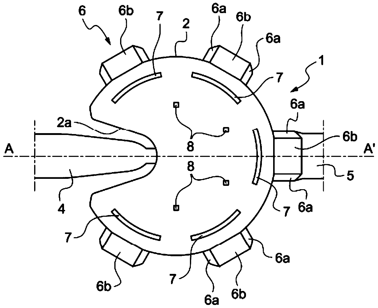
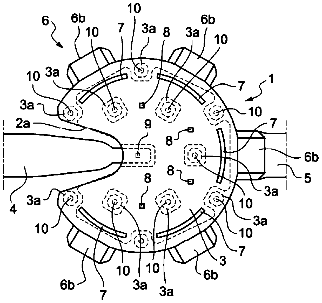
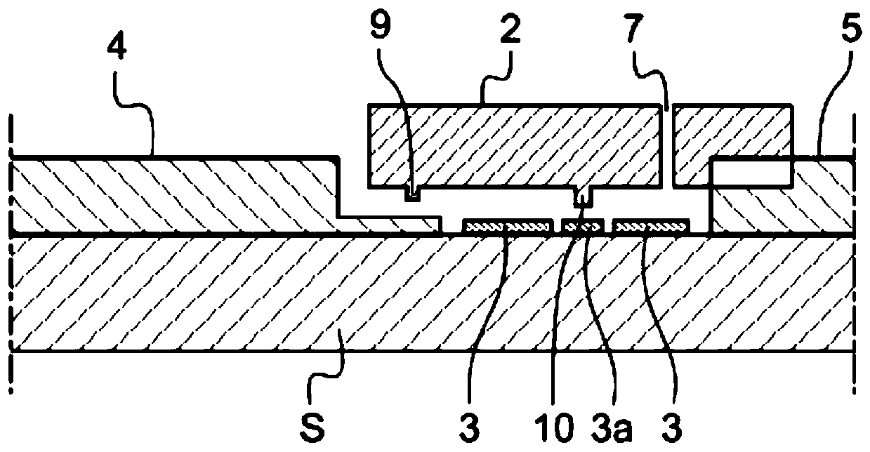
[0054] if reference Figure 1 to Figure 4 , it can be noted that it shows a microelectromechanical (MEMS) switch 1 according to the invention.

[0055] The MEMS switch 1 is formed on a substrate S, and mainly includes a deformable conductive film 2 , an actuation electrode 3 , a signal input line 4 and a signal output line 5 .

[0056] Signal input lines 4 , signal output lines 5 and actuation electrodes are formed on the substrate S. As shown in FIG.

[0057] The deformable conductive membrane 2 is planar, generally circular, with radial openings 2a in the direction of the signal input line 4, so that the periphery of the deformable conductive membrane 2 narrows towards the center. The deformable conductive film 2 is suspended by anchors 6 on the actuation electrodes 3 distributed on its periphery, so as to concentrate the least rigid area of ​​the deformable conductive film 2 at the contact recess, where the signal input lines 4 (to be described below) are arranged At a po...


PUM


Abstract

The invention relates to a microelectromechanical system switch (1), comprising a signal input line (4), a signal output line (5), a deformable conductive film (2) electrically connected to the line (5), and including a facing line ( 4) the contact recess (9), the actuation electrode (3) of the membrane (2), characterized in that the membrane (2) has a planar circular shape with a radial direction in the direction of the signal input line (4) an opening (2a), which narrows from the periphery of the membrane (2) towards the center, a contact recess (9) is formed in the central area of ​​the membrane (2), the actuation electrode (3) has the same shape as the membrane (2), And the gap between the membrane (2) and the actuation electrode (3) is only an air gap, wherein the membrane (2) faces the actuation electrode (3).

Description

technical field [0001] The invention relates to the field of microelectromechanical systems (MEMS), in particular to a microelectromechanical switch. Background technique [0002] International patent applications WO2006 / 023724, WO2006 / 023809, WO2007 / 022500 and WO2007 / 022500 as well as US patent applications US 2012 / 031744A1 and US2010 / 181631A1 describe MEMS switches according to the prior art. [0003] Radio frequency microelectromechanical systems (RF MEMS) allow switching operations for applications covering a wide range of frequencies (DC-100GHz). Their competitive advantages in terms of their performance, and their low power consumption with respect to their size make them highly appreciated components by system builders. [0004] However, in order for these components to be incorporated into electronic systems, they must provide some mechanical and thermal stability. [0005] For example, prolonged actuation of the component should not produce permanent deformation o...

Claims


Application Information

Patent Timeline
Patent Type & Authority Patents(China)
IPC IPC(8): H01H59/00
CPCH01H59/0009H01H2059/0072H01H51/22
Inventor 皮埃尔·布隆迪罗曼·斯特凡尼尼L·Y·张阿贝杜勒·哈利姆·察尔
Owner AIRMEMS
Learn More