Hydraulic system and rotary drilling rig comprising same

A hydraulic system and hydraulic technology, applied in the field of rotary drilling rigs, can solve the problems of high pressure of the pressurized oil cylinder 140, the increase of the hydraulic oil of the pressurized oil cylinder 140, and the follow-up of load parts, so as to reduce power loss and improve the Overall efficiency, effect of avoiding overheating

Active Publication Date: 2010-06-09
BEIJING SANY HEAVY MASCH CO LTD
View PDF0 Cites 36 Cited by
  • Summary
  • Abstract
  • Description
  • Claims
  • Application Information

AI Technical Summary

Problems solved by technology

When the speed at which the power head 150 moves downward is equal to the extension speed of the piston, the pulling force produced by the power head 150 on the piston remains zero; when the speed at which the power head 150 moves downward is greater than the extension speed of the piston, the power head 150 Generate a pulling force on the piston, and this pulling force will force the piston to go down; in actual operation, the pulling force generated by the power head 150 is very large, which will cause the hydraulic oil in the pressurized cylinder 140 to rise, causing the pressurized cylinder 140 or the hydraulic system due to excessive pressure. high and damaged
[0009] The above-mentioned rotary drilling rig in the prior art cannot keep the synchronous action of the piston and the power head 150, and cannot avoid the pulling force of the power head 150 on the piston, so that the above-mentioned rotary drilling rig cannot perform construction operations in accordance with the CFA construction method
Therefore, the above-mentioned rotary drilling rig has the defect that the application mode is single
[0010] The reason for the single application mode of the above-mentioned rotary drilling rig is that the hydraulic power provided by the hydraulic system cannot make the piston of the pressurized cylinder 140 and the power head 150 move synchronously, and, due to the existence of the self-locking mechanism, the pressurized cylinder 140 cannot follow the load. Floating, unable to keep the pressurized cylinder 140 moving with the load parts
In the hydraulic systems with self-locking mechanisms of other construction machinery, there is also the problem that the hydraulic actuators cannot follow the load parts according to the needs of the environment.

Method used


Image

  • Hydraulic system and rotary drilling rig comprising same
  • Hydraulic system and rotary drilling rig comprising same
  • Hydraulic system and rotary drilling rig comprising same

Examples


Embodiment 1

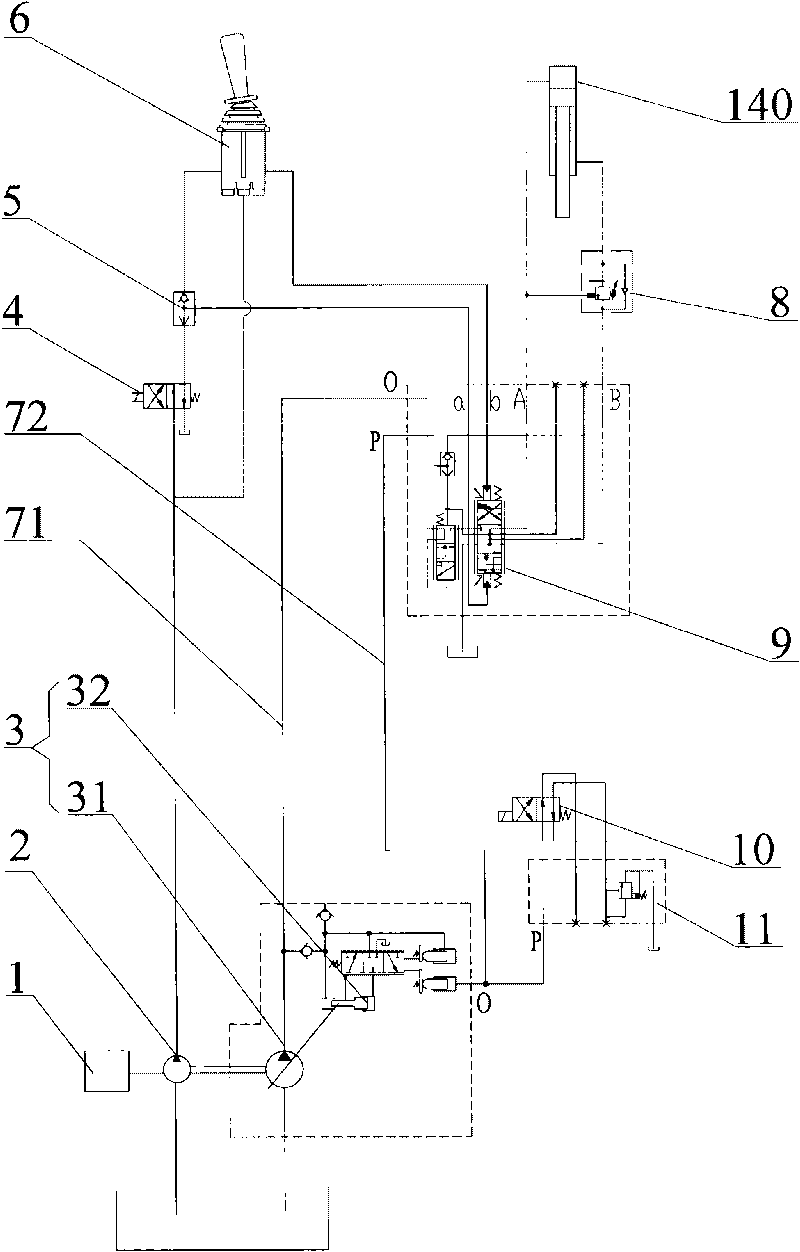
[0038] The hydraulic system provided in Embodiment 1 includes a main hydraulic circuit and an auxiliary hydraulic circuit. The main hydraulic circuit forms the power output part of the hydraulic system, and the auxiliary hydraulic circuit forms the control part of the hydraulic system to control the state of the main hydraulic circuit.

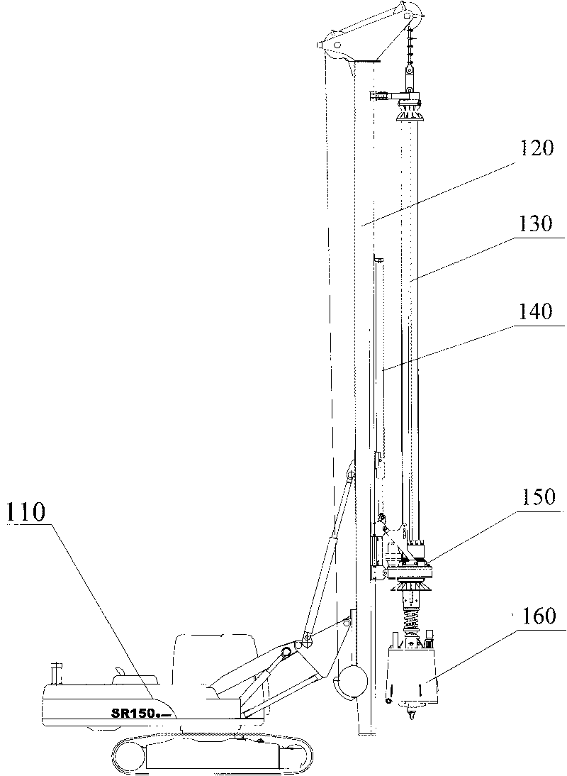
[0039] As shown in the figure, the main hydraulic circuit includes a hydraulic pump 3 , a pressurized oil cylinder 140 , and a reversing valve 9 . In this example, the hydraulic pump 3 is a load-sensing pump, which is driven to rotate by the engine 1 to output hydraulic power; the load-sensing pump includes a variable hydraulic pump 31 and a hydraulic compensation mechanism 32 for controlling the displacement of the variable hydraulic pump 31 . The main hydraulic circuit includes an oil supply pipeline 71 and a feedback pipeline 72, the oil supply pipeline 71 is connected between the oil supply port of the variable hydraulic pump 31 and the rev...

Embodiment 2

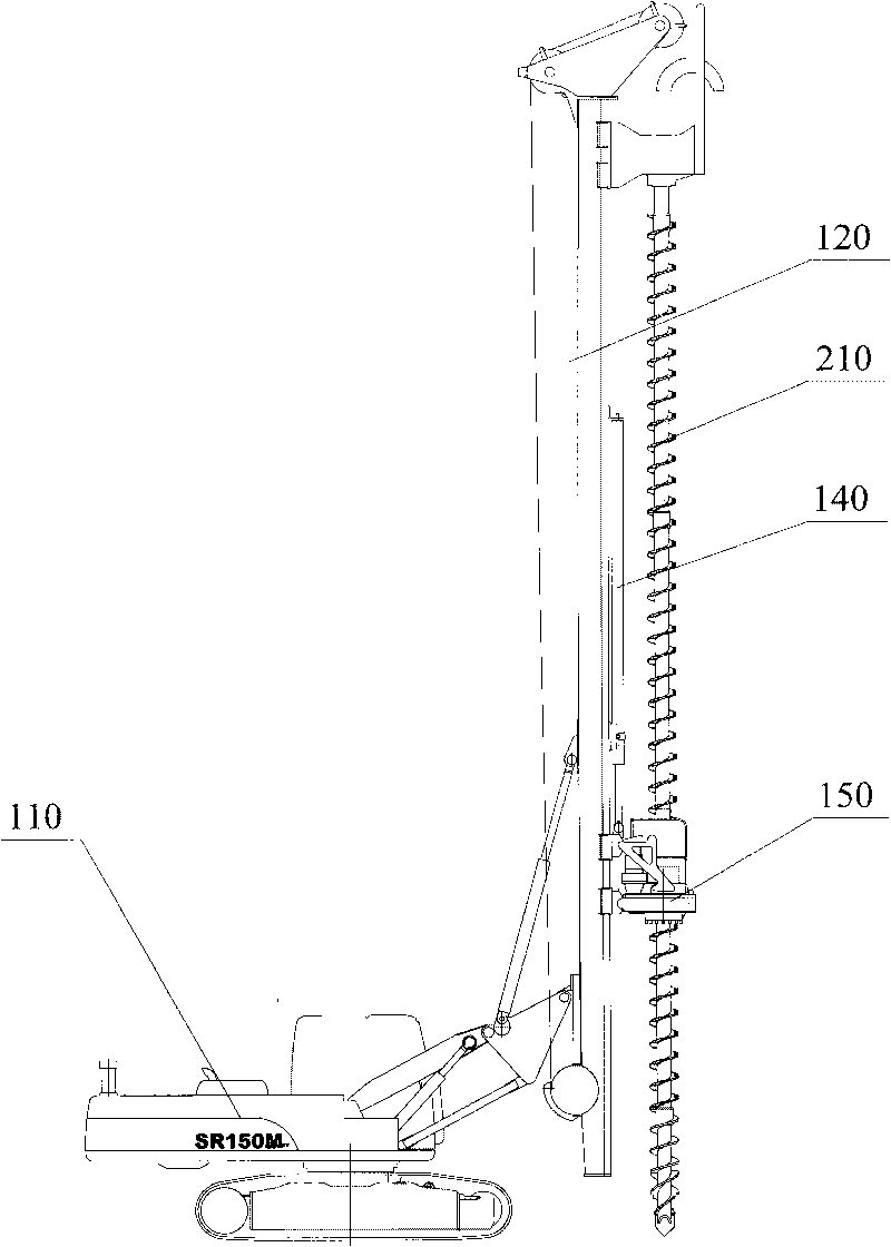
[0057] The working principle of the second embodiment is: when the pressurized oil cylinder 140 needs to be followed, the follow-up control valve 10 is placed in the left position, and the oil inlet port of the follow-up control overflow valve 11 communicates with the oil supply port of the hydraulic pump 3. , adjust the overflow pressure of the follow-up control overflow valve 11 so that the maximum pressure of the main oil pipeline 71 is equal to the overflow pressure, and the excess hydraulic oil flows back to the hydraulic oil tank through the follow-up control overflow valve 11; and the pressurized oil cylinder The force exerted by the power head 150 on the power head 150 is equal to the force exerted by the power head 150 on the piston of the pressurized oil cylinder 140 to maintain the force balance of the piston; the piston is stretched out at a predetermined speed; The downward moving speed of the head 150 remains equal, and the follow-up of the pressurized oil cylinde...

Embodiment 3

[0061] The working principle of the hydraulic system provided by Embodiment 3 is as follows:

[0062] When the rotary drilling rig provided with the hydraulic system in this example performs construction operations in uneven soil according to the CFA method mode, when the feed speed of the long helical drill rod 210 increases, the speed at which the power head 150 moves down also increases. , the pressure in the rodless chamber of the pressurized cylinder 140 will decrease; at this time, the controller obtains the information of the pressure change in the rodless chamber detected by the pressure sensor 12, and then determines the overflow pressure according to a predetermined strategy, and sends it to the follow-up control overflow. Flow valve 11 outputs a corresponding electric signal, so that the follow-up control overflow valve 11 adjusts its overflow pressure according to the corresponding electrical signal, so that the pressure at the induction port O of the hydraulic comp...


PUM


Abstract

The invention discloses a hydraulic system and a rotary drilling rig comprising the same. The disclosed hydraulic system comprises a main hydraulic circuit, wherein the main hydraulic circuit comprises a hydraulic pump, a hydraulic actuator and a reversing valve; the reversing valve is connected between the hydraulic pump and a pressure oil cylinder; and a self-locking mechanism is arranged between two hydraulic chambers of the hydraulic actuator. Compared with the prior art, the hydraulic system also comprises a follow-up control valve and a follow-up control overflow valve, wherein the follow-up control valve is connected between an oil inlet of the follow-up control overflow valve and the main hydraulic circuit. In the disclosed hydraulic system, when the oil inlet of the follow-up control overflow valve is communicated with the main hydraulic circuit, the overflow pressure of the follow-up control overflow valve can be reflected on the main hydraulic circuit; and the action speed of the hydraulic actuator is adjusted by influencing the flow quantity of hydraulic oil which is supplied to the hydraulic actuator by the main hydraulic circuit, so that the hydraulic actuator keeps synchronous action with a load part to realize the follow-up of the hydraulic actuator and the load part.

Description

technical field [0001] The present invention relates to a hydraulic control technology, in particular to a hydraulic system, and also to a rotary drilling rig with the hydraulic system. Background technique [0002] Pile machinery is a mechanical equipment used in the construction of various pile foundations, foundation improvement and reinforcement, underground retaining diaphragm walls, underground anti-seepage diaphragm walls, and other special foundation foundations. Its function is to bury various foundation piles into the soil In order to improve the bearing capacity of the foundation. There are two basic types of foundation piles: prefabricated piles and cast-in-situ piles; the former are buried in the soil with piling machinery, and the latter are formed by drilling deep holes with a drilling machine and pouring concrete. [0003] At present, the rotary drilling rig is an important pile-type machine; when performing pile foundation construction, the rotary drilling ...

Claims


Application Information

Patent Timeline
Patent Type & Authority Applications(China)
IPC IPC(8): F15B15/18F15B13/02E21B3/00
CPCF15B2211/329F15B2211/6313F15B2211/20553F15B9/04F15B2211/50581E21B7/022
Inventor 黎中银胡堂堂饶玉章
Owner BEIJING SANY HEAVY MASCH CO LTD
Why Eureka
Try Eureka