Rotation detector attachment decelerating device

A technology of rotation detector and deceleration device, which is applied in the direction of measuring device, electromechanical device, transmission device, etc., can solve the problem of high cost of rotation detector, achieve low cost, low cost, and improve detection accuracy

A technology of rotation detector and deceleration device, which is applied in the direction of measuring device, electromechanical device, transmission device, etc., can solve the problem of high cost of rotation detector, achieve low cost, low cost, and improve detection accuracy

CN101725688BActive Publication Date: 2012-11-14SUMITOMO HEAVY IND LTD

Image

  • Rotation detector attachment decelerating device
  • Rotation detector attachment decelerating device
  • Rotation detector attachment decelerating device

Examples


Embodiment Construction

[0021] Hereinafter, an example of an embodiment of the present invention will be described in detail with reference to the drawings.

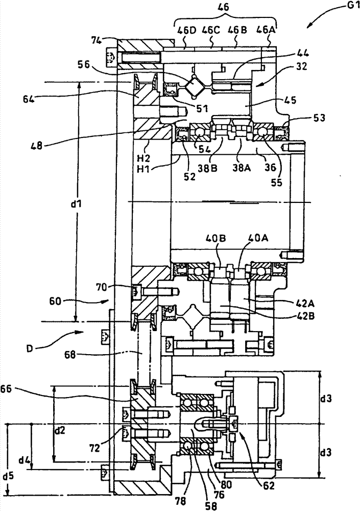
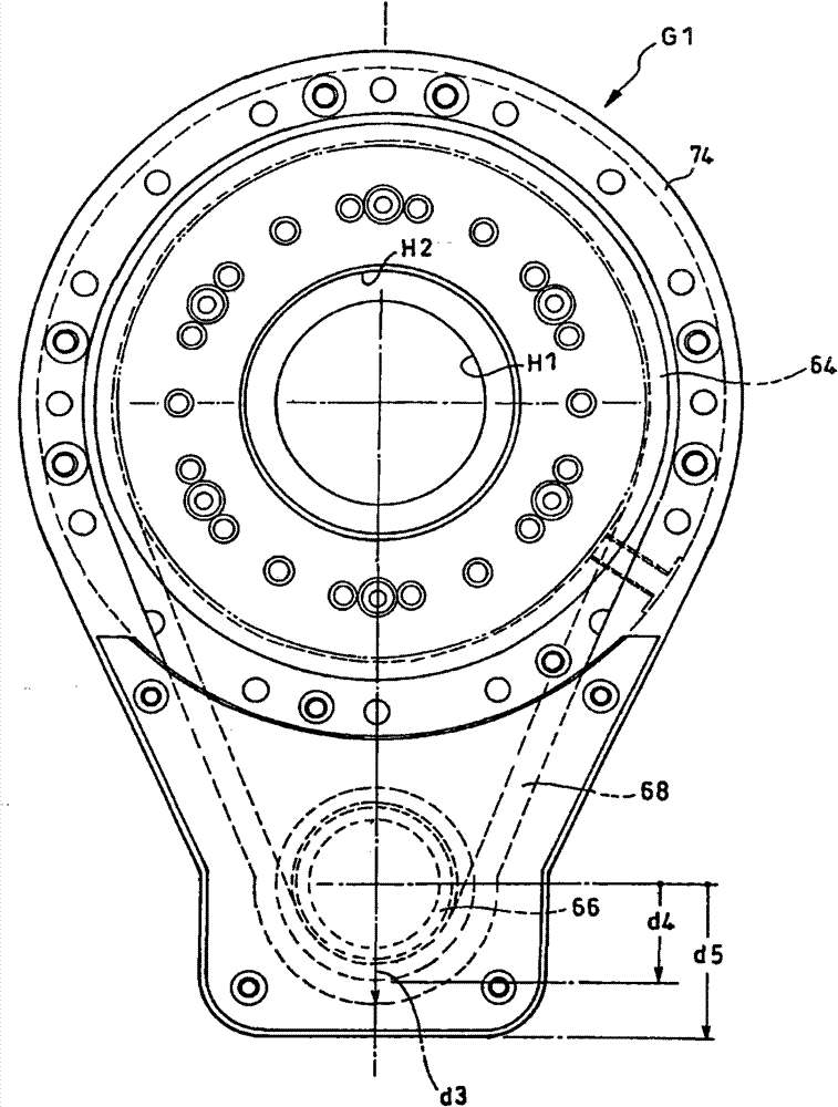
[0022] exist figure 1 and figure 2 An example of a reduction gear transmission with a rotation detector according to an embodiment of the present invention is shown.

[0023] This reduction gear G1 is a device having a reduction unit (reduction mechanism unit) 32 of a so-called oscillating internal meshing planetary gear structure, and is a hollow type reduction gear having a hollow portion H1 penetrating in the axial direction at the central portion of the reduction unit 32 in the radial direction. device.

[0024] The reduction gear G1 includes: an input shaft 36 having the hollow portion H1; eccentric bodies 38A, 38B formed integrally with the input shaft 36; The external gears 42A, 42B and the internal gear 44 internally mesh with the external gears 42A, 42B.

[0025] The external gears 42A, 42B and the internal gear 44 have an extrem...


PUM


Abstract

A rotation of an output shaft of a decelerating device is highly precisely detected at a low cost. Provided is a rotation detector attachment decelerating device G1 having a function of detecting a rotation of an output block (output shaft) 48, the rotation detector attachment decelerating device including: an auxiliary rotation shaft 58 which is disposed in parallel to an output block (output shaft) 48; rotation transmitting means 60 for transmitting a rotation of the output block 48 to the auxiliary rotation shaft 58; and an encoder (rotation detector) 62 which detects a rotation of the auxiliary rotation shaft 58, wherein the rotation of the output block 48 is detected by detecting the rotation of the auxiliary rotation shaft 58 through the encoder 62.

Description

technical field [0001] This application claims priority based on Japanese Patent Application No. 2008-274472 filed on October 24, 2008. The entire content of this application is incorporated in this specification by reference. [0002] The present invention relates to a reduction gear with a rotation detector attached. Background technique [0003] For example, disclosed in Patent Document 1 as Figure 7 Gear unit G0 with rotation detector shown. The reduction gear G0 is a so-called eccentric swinging internal engagement type device, and includes, as a reduction mechanism part: a first shaft 14 coaxial with the input shaft 12 and disposed so as to surround the input shaft 12; a second shaft 16, coaxial with the first shaft 14 and arranged to surround the first shaft 14; and bearings 18 and 20 interposed between the first shaft 14 and the second shaft 16 and assembled into the first shaft 14 and the second shaft 16 is rotatably supported on the other side; in addition, a s...

Claims


Application Information

Patent Timeline
14 Nov 2012
Publication
CN101725688B
IPC
F16H37/02; G01D5/245; H02K7/10
CPC
G01D11/30; G01D5/245; F16H1/32; H02K7/10; H02K11/00
Inventors
芳贺卓; 志津庆刚