A ink ribbon unit with supporting device and image printing equipment

A technology for supporting devices and printing equipment, which is applied in printing, inking devices, transfer materials, etc., can solve the problems of increased manufacturing cost and high cost, and achieve the effect of simplified structure and simple structure

Inactive Publication Date: 2005-02-09
SHARP KK
View PDF1 Cites 3 Cited by
  • Summary
  • Abstract
  • Description
  • Claims
  • Application Information

AI Technical Summary

Problems solved by technology

Another problem with the conventional configuration is that the combination of the rotation amount detection means (encoder) causes an increase in the manufacturing cost of the equipment, because the provision of the parts increases the number of constituent elements, and these parts are expensive high-precision parts

Method used


Image

  • A ink ribbon unit with supporting device and image printing equipment
  • A ink ribbon unit with supporting device and image printing equipment
  • A ink ribbon unit with supporting device and image printing equipment

Examples


Embodiment Construction

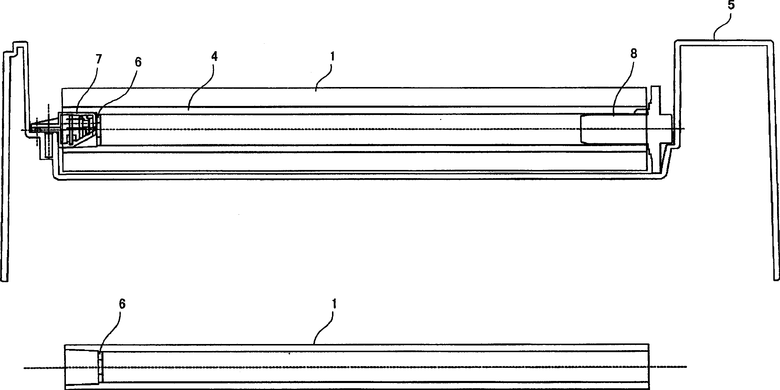
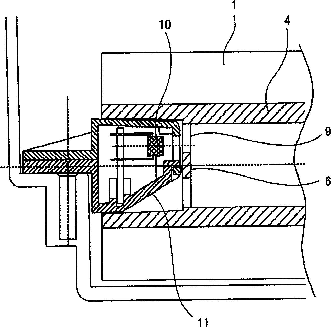
[0020] A tape support device and a structured ink ribbon unit for an image printing apparatus according to a preferred embodiment of the present invention will now be described in detail with reference to the accompanying drawings. figure 1 is a cross-sectional view of the ribbon support and structured ribbon unit, and figure 2 It is an enlarged cross-sectional view showing a part of the belt support device.

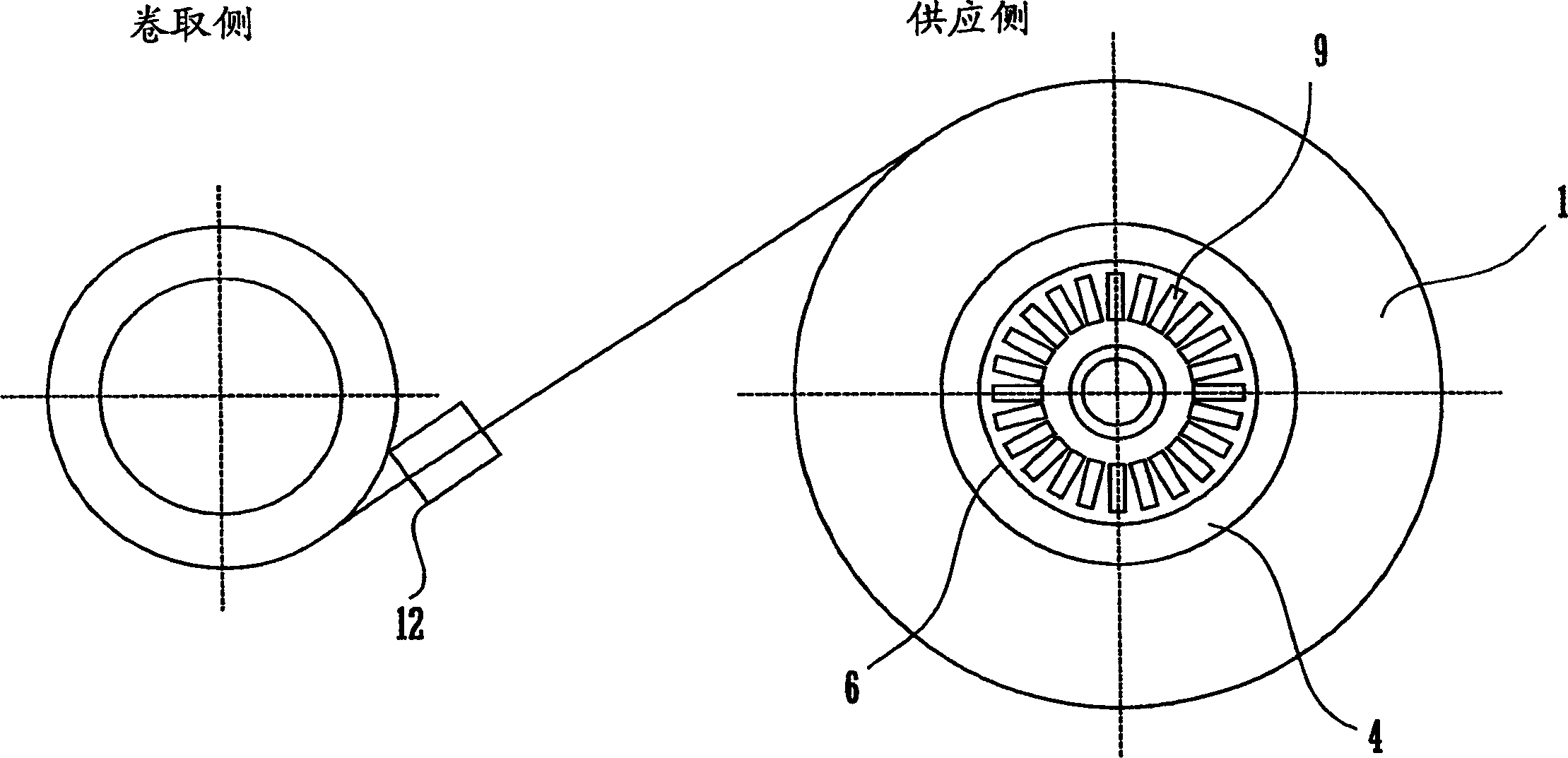
[0021] The structured ink ribbon unit includes a hollow ribbon core 4 and a rolled ink ribbon 1 wound in a cylindrical form around the core 4 . Inside the tape core 4 , at a certain distance from one end of the tape core 4 , a partition disc 6 is mounted. A large number of radially arranged narrow openings or slots 9 are formed in the separating disc 6 . On the outside of the partition disc 6, there is provided a core support member 11 mounted in the cylindrical hole of the tape core 4 and supporting the tape core 4, the tape core support member 11 incorporating a re...


PUM


Abstract

A ribbon support device for rotatably supporting a rolled ink ribbon includes a partitioning disk mounted in a terminal part of a ribbon core on which the ink ribbon is wound, the partitioning disk having a plurality of slits formed therein, and a reflection-type photoelectric sensor for detecting the slits, the sensor being located at a position facing the slits. Each rotation of the ribbon core is detected when the reflection-type photoelectric sensor has detected all the slits formed in the partitioning disk. The length of the ink ribbon supplied by one rotation of the ink ribbon is calculated by counting the amount of feed of a ribbon feeding stepping motor per rotation of the ribbon core.

Description

technical field [0001] The present invention generally relates to an image printing apparatus such as a copier and a printing machine that uses a roll-type ink ribbon. More particularly, the present invention relates to a compact and low-cost arrangement for detecting the amount of unused portion of an ink ribbon and whether the ink ribbon is securely installed in an image printing apparatus. Background technique [0002] Figure 4 A well-known structure of an image printing apparatus such as a facsimile machine or a printing machine using a roll ink ribbon is shown. Figure 4 The structure consists of a supply spool wound with the unused portion of the ink ribbon and a take-up spool wound with the used portion of the ink ribbon. [0003] The image printing device includes a thermal head and an impression roller located in the surrounding area of ​​the ink ribbon to transfer the ink to the printing paper. Generally, image printing equipment is constructed in such a way that...

Claims


Application Information

Patent Timeline
Patent Type & Authority Applications(China)
IPC IPC(8): B41J17/36B41J35/36
CPCB41J35/36B41J17/36
Inventor 须田隆三宅秀幸白石贤一西川孝富
Owner SHARP KK
Why Eureka
Try Eureka