
Stepping motor control circuit and analogue electronic watch

A stepper motor and control circuit technology, applied in the field of stepper motor control circuits and analog electronic clocks, can solve the problem of difficulty in correctly determining the rotation status and the like

Inactive Publication Date: 2011-06-29
SEIKO INSTR INC
View PDF2 Cites 8 Cited by
  • Summary
  • Abstract
  • Description
  • Claims
  • Application Information

AI Technical Summary

Problems solved by technology

[0005] However, if the rotation status of the stepping motor is judged only based on whether the generation timing of the induction signal VRs is earlier or later than the reference time, there is a problem that when the energy of the main drive pulse changes with respect to the load, Difficulty judging rotation conditions correctly

Method used


Image

  • Stepping motor control circuit and analogue electronic watch
  • Stepping motor control circuit and analogue electronic watch
  • Stepping motor control circuit and analogue electronic watch

Examples


Embodiment Construction

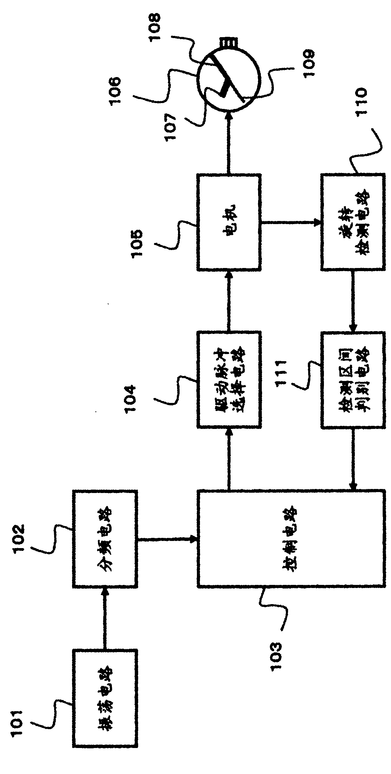
[0033] figure 1 It is a block diagram commonly used in an analog electronic timepiece using a motor control circuit according to each embodiment of the present invention, showing an example of an analog electronic wristwatch.

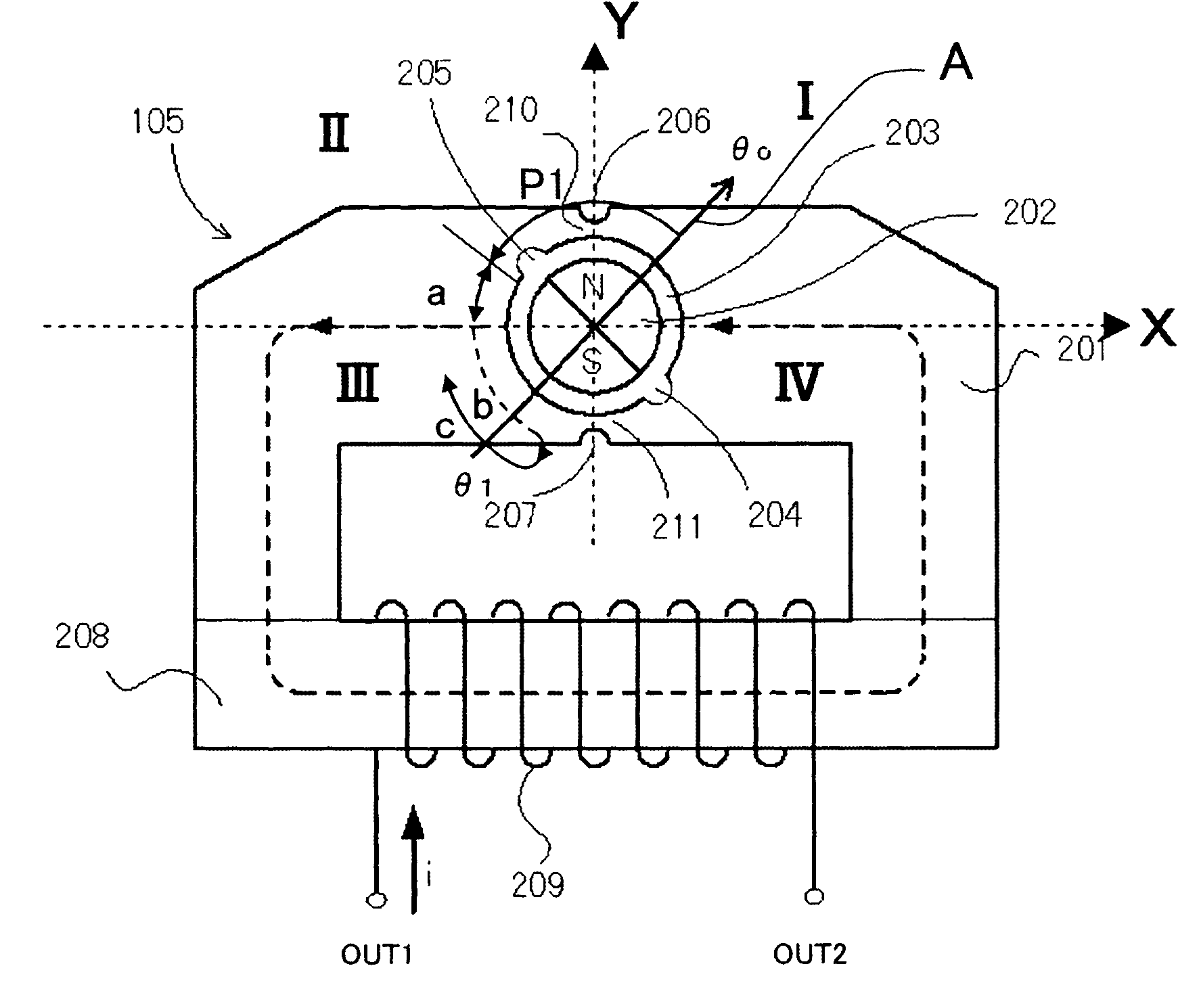
[0034] exist figure 1 Among them, the analog electronic clock has: an oscillating circuit 101, which generates a signal of a predetermined frequency; a frequency dividing circuit 102, which divides the frequency of the signal generated by the oscillating circuit 101, and generates a clock signal as a time reference; a control circuit 103, which constitutes The control of each circuit element of the electronic watch or the change control of the driving pulse; the driving pulse selection circuit 104, which selects and outputs the driving pulse for motor rotation according to the control signal from the control circuit 103; the stepping motor 105, whose Utilize the driving pulse from driving pulse selection circuit 104 to carry out rotational drive; Analo...


PUM


Abstract

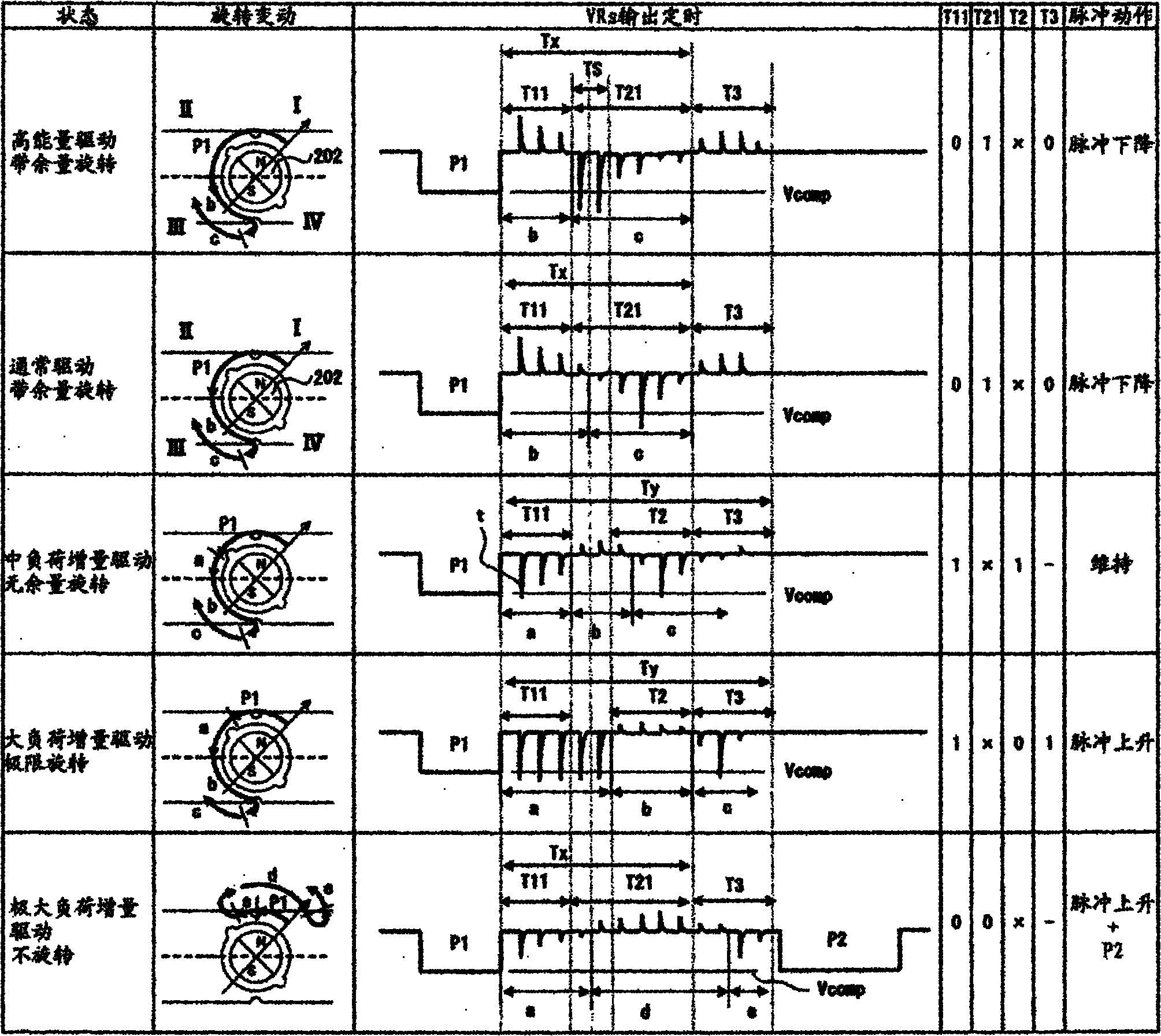
The present invention provides a stepping motor control circuit and an analogue electronic watch. The invention enables accurate detection of the state of rotation even when the timing of generation of an induced signal is changed due to the relative change of drive energy with respect to a load. As solutions, a plurality of types of detection segments are provided as the detection segments for detecting the state of rotation of a stepping motor (105), and a control circuit (103) selects one of the detection segments, determines the state of rotation of the stepping motor(105) using a detection pattern of an induced signal (VRs) in the selected detection segment according to the extent of the reserve driving capacity of a main drive pulse (P1), and controls the driving of the stepping motor (105) on the basis of any one of a plurality of the main drive pulses (P1) having energies different from each other or a correction drive pulse (P2) having energy larger than the respective main drive pulses (P1)on the basis of the result of determination.

Description

technical field [0001] The invention relates to a stepping motor control circuit and an analog electronic clock using the stepping motor control circuit. Background technique [0002] Conventionally, a stepping motor having a stator having a rotor housing hole and a positioning portion for determining a stop position of the rotor, and a rotor arranged in the rotor housing hole has been used in analog electronic clocks and the like. and a coil to which the stepping motor provides an alternating signal to cause the stator to generate magnetic flux, thereby rotating the rotor and stopping the rotor at a position corresponding to the positioning portion. [0003] As the control method of the stepping motor, the following correcting driving method has been used, that is, when the stepping motor is driven by the main driving pulse P1, it is detected by detecting the induction signal VRs generated by the stepping motor. Rotation has occurred, and depending on whether rotation has ...

Claims


Application Information

Patent Timeline
Patent Type & Authority Applications(China)
IPC IPC(8): G04C3/14
CPCG04C3/143
Inventor 间中三郎高仓昭小笠原健治佐久本和实本村京志山本幸祐清水洋神山祥太郎
Owner SEIKO INSTR INC
Learn More