Single degree-of-freedom optical fiber ring depolarization method

A technology of optical fiber ring and degree of freedom, applied in the field of optical fiber ring, can solve the problems of poor stability and inconvenience, and achieve the effect of simple and easy to use

Inactive Publication Date: 2012-10-31
SHANGHAI UNIV
View PDF0 Cites 0 Cited by
  • Summary
  • Abstract
  • Description
  • Claims
  • Application Information

AI Technical Summary

Problems solved by technology

Therefore, in practical applications, it is very inconvenient to adjust the polarization conversion of the fiber ring with three degrees of freedom for different polarization states of incident light, and the stability is poor.

Method used


Image

  • Single degree-of-freedom optical fiber ring depolarization method
  • Single degree-of-freedom optical fiber ring depolarization method
  • Single degree-of-freedom optical fiber ring depolarization method

Examples


Embodiment 1

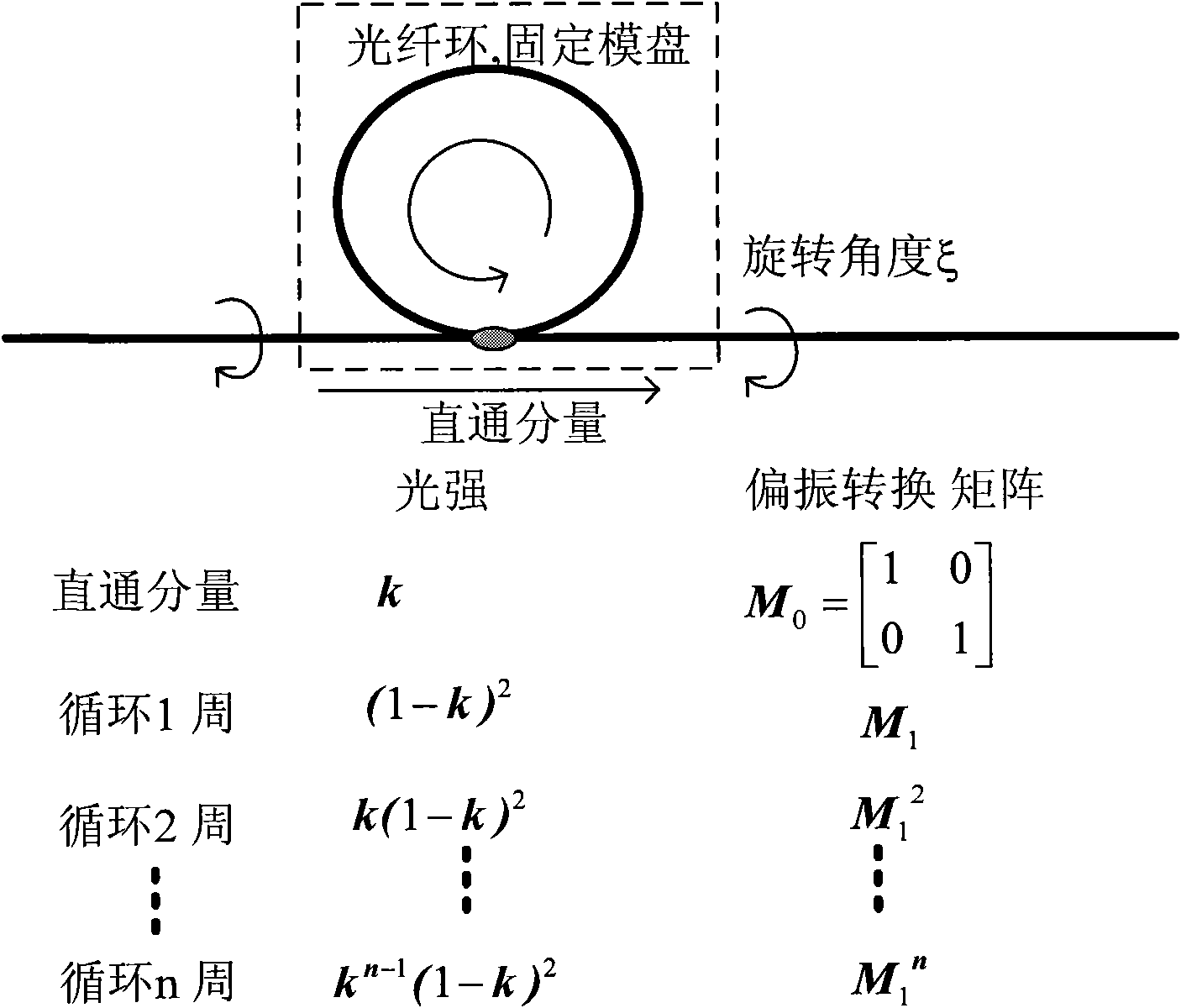
[0025] Embodiment one: see figure 1 . A single-degree-of-freedom fiber ring depolarization method is characterized in that: the depolarizer is composed of a single-mode fiber ring with a length greater than the coherence length of the depolarized light and a 2×2 single-mode fiber coupler, and the fiber ring and the coupler are not considered In the case of loss, the optimal splitting ratio of the fiber coupler is 1:2; the fiber in the fiber ring passes through the coiling method, so that the birefringence effect introduced by the fiber by bending and twisting has the polarization conversion effect of a half-wave plate; the fiber ring converts the input light Decomposed into straight-through light and light components with different number of cycles, the fiber ring has the function of polarization decomposition of the input light, in which the through-light and the light components of even-numbered cycles have the same polarization state, while the light components of odd-numbe...

Embodiment 2

[0026] Embodiment 2: This embodiment is basically the same as Embodiment 1, and the special features are:

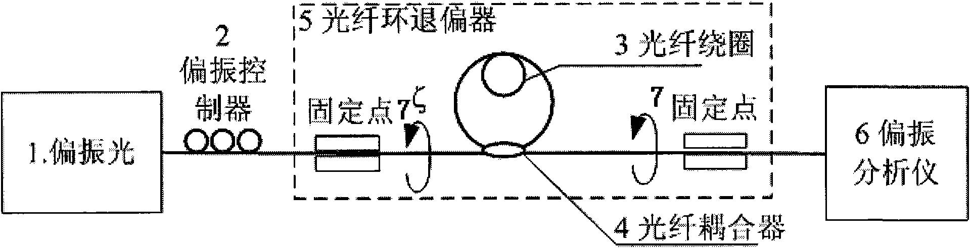
[0027] (1) Realization of depolarization: see figure 2 . The specific method is: the polarized light 1 first passes through the polarization controller 2, and the polarization controller is used to adjust the polarization state of the input light to test that the depolarizer has a corresponding rotation angle for all polarization states to achieve depolarization. According to the coherence length of polarized light, cut off the fiber of appropriate length, according to formula (9) and β=(π / λ)EC(r / R) 2 , calculate the appropriate bending radius of the fiber, and wind it into a fiber coil with the function of a half-wave plate 3. When the fiber is coiled, it is necessary to pay attention to as little twisting as possible to meet the condition that the torsional birefringence is much smaller than the bending birefringence. To judge whether the optical fiber coil meets th...


PUM


Abstract

The invention relates to a single degree of freedom optical fiber ring depolarization method. Bending double refraction and torsion double refraction are performed on optical fibers in an optical fiber ring, and then the polarization conversion has the polarization conversion characteristic of a half wave plate, thus the common monomode optical fiber can realize the polarization separation of incident light. The input light is decomposed into two groups by the optical fiber ring in the two polarization directions, the strengths of the two groups of light can be equal through optimally designing the coefficients of a coupler, and the components of the decomposed light are not coherent by designing the length of the optical fiber ring to be greater than the coherence length of the depolarized light source. Therefore, by adjusting the torsion angle of the optical fiber ring, the relative position of the polarization states of the two groups of light is changed. When the vector of polarization state of the incident light is mutually perpendicular to the polarization conversion vector of the optical fiber ring, the polarization states of the two groups of light are mutually orthogonal,and then the depolarization of the light is realized. The light with any depolarization has one torsion angle, and then the depolarization of the light is realized.

Description

technical field [0001] The invention relates to a method for realizing depolarization by adjusting a single parameter (degree of freedom) for input light with different polarizations, in particular to a fiber ring composed of a single-mode fiber coupler and a single-mode fiber, and splitting light through the coupler The optimal design of the ratio; adjust the coiling of the fiber in the ring, so that the birefringence effect caused by the bending and twisting of the fiber can realize the half-wave plate effect of polarization conversion; for the input light of different polarization states, the depolarization of the light can be realized through the twisting of the fiber ring Methods. Background technique [0002] Polarization random perturbation is a problem that has plagued high bit rate optical communication and optical sensing systems for a long time. In the optical communication system, it manifests as the effects of polarization dispersion and polarization loss of li...

Claims


Application Information

Patent Timeline
Patent Type & Authority Patents(China)
IPC IPC(8): G02B6/27
Inventor 王春华李力王廷云宋岩魏硕任倩倩
Owner SHANGHAI UNIV
Why Eureka
Try Eureka