Descending control channel assignment and blind test method

A technology of control channel and allocation method, which is applied in the design of downlink control information format, blind detection of downlink control channel by user equipment, design of downlink control channel of LTE-Advanced system, and can solve problems such as waste of resources

Inactive Publication Date: 2013-10-16
SHARP KK
View PDF0 Cites 0 Cited by
  • Summary
  • Abstract
  • Description
  • Claims
  • Application Information

AI Technical Summary

Problems solved by technology

The purpose of the present invention is to effectively solve the problem of resource waste that may be caused by multi-segment PDCCH allocation and multi-segment PDCCH blind detection due to the fact that the LTE-Advanced system bandwidth is composed of multiple carrier frequencies

Method used


Image

  • Descending control channel assignment and blind test method
  • Descending control channel assignment and blind test method
  • Descending control channel assignment and blind test method

Examples


Embodiment 1

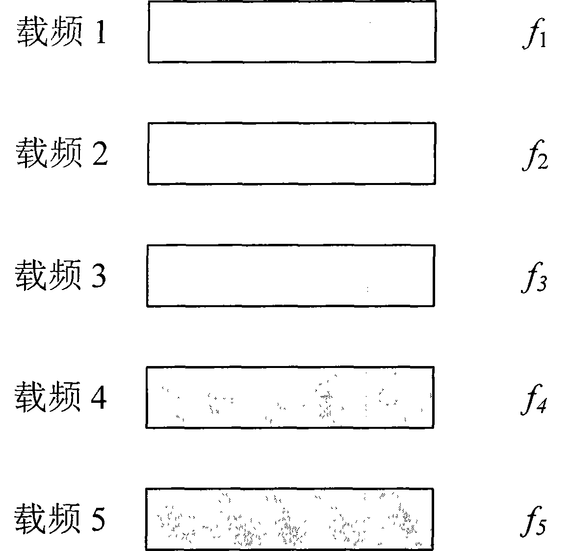
[0125] An improved DCI format is introduced for LTE-Advanced user equipment to perform blind detection on the basic carrier frequency. An improved method is to add a field in the originally defined DCI format to indicate the carrier frequency where the user's PDCCH information is located. The originally defined DCI format may be the DCI format defined in LTE, and / or the DCI format newly introduced by the LTE-Advanced system for blind detection of non-basic carrier frequency. In this example, the DCI format defined in LTE is the originally defined DCI format. Such as figure 1As shown, the system bandwidth includes 5 carrier frequencies, so each DCI format needs to add a 5-bit field, and the corresponding improved DCI formats are respectively named Format0', Format1', Format1A', Format1B', Format1C', Format1D', Format2' and Format2A'.

[0126] In order to better illustrate the improved DCI format, Format1A' is taken as an example below to describe each field in detail.

[0...

Embodiment 2

[0177] An improved DCI format is introduced for LTE-Advanced user equipment to perform blind detection on the basic carrier frequency. An improved method is to add a field in the originally defined DCI format to indicate the carrier frequency where the user's PDCCH information is located. The originally defined DCI format may be a DCI format defined in LTE, and / or a DCI format newly introduced by the LTE-Advanced system for blind detection of non-basic carrier frequencies. In this example, the DCI format defined in LTE is the originally defined DCI format. Such as figure 1As shown, the system bandwidth includes 5 carrier frequencies, so each DCI format needs to add a 5-bit field, and the corresponding improved DCI formats are respectively named Format0", Format1", Format1A", Format1B", Format1C", Format1D", Format2" and Format2A".

[0178] In order to better illustrate the improved DCI format, the following takes Format1A" as an example to describe each field in detail.

...

Embodiment 3

[0231] On the basis of the above improved DCI format, a new DCI format is introduced for LTE-Advanced user equipment to perform blind detection on the basic carrier frequency, which is named Format X in this example. This format contains only one PDCCH index information, 4 bits.

[0232] The corresponding relationship between the DCI format and the transmission mode used by the LTE-Advanced user equipment for blind detection on the basic carrier frequency can be described by the following table 4 or table 5:

[0233] Table 4

[0234] transfer mode Refer to the DCI format 1 1', 1A', X 2 1', 1A', X 3 2A', X 4 2’,X 5 1D',X 6 1B',X 7 1', 1A', X

[0235] table 5

[0236] transfer mode Refer to the DCI format 1 1", 1A", X 2 1", 1A", X 3 2A", X 4 2”,X 5 1D", X 6 1B", X 7 1", 1A", X

[0237] The above table is for example only, and the present invention is not limited t...


PUM


Abstract

The invention provides a design and a test method for a descending control channel in an LTE-Advanced system, particularly a descending control channel assignment method for a base station and a descending control channel blind test method for user equipment. PDCCH index information is introduced to a general DCI format according to the invention, which is used for the blind test on basal carrier frequency, the user equipment realizes the rapid effective blind test course through the PDCCH index information, and the frequency of the blind test and the required power consumption are effectively reduced.

Description

technical field [0001] The invention relates to the technical field of mobile communication, in particular to the design of the downlink control channel of the LTE-Advanced system, the design of the format of the downlink control information, and a method for user equipment to perform blind detection on the downlink control channel. According to the present invention, a downlink control channel (PDDCH) allocation method for base station (eNB) and a downlink control channel (PDDCH) blind detection method for user equipment (UE) are proposed. Background technique [0002] Ericsson discussed four possible designs of four different downlink control channels in the LTE-Advanced system at the 3GPP TSG RAN WG153bis meeting (R1-082468, Carrier aggregation in LTE-Advanced, 3GPP TSG RANWG153bis, Warsaw, Poland, June30- July4, 2008). The first solution is to independently allocate a PDCCH on each component carrier, which is used to indicate the allocation information of the PDSCH on t...

Claims


Application Information

Patent Timeline
Patent Type & Authority Patents(China)
IPC IPC(8): H04W28/06H04W72/12H04L1/00
CPCY02D30/70
Inventor 黄磊刘仁茂丁铭陈晨孙国林张应余
Owner SHARP KK
Why Eureka
Try Eureka