CT scanning equipment

一种CT扫描、设备的技术,应用在电脑断层扫描仪、回波层析、放射诊断数据传输等方向,能够解决成本高、不能满足稳定性要求等问题,达到降低成本、简化传输路径的效果

Inactive Publication Date: 2010-06-16
GE MEDICAL SYST GLOBAL TECH CO LLC
View PDF0 Cites 6 Cited by
  • Summary
  • Abstract
  • Description
  • Claims
  • Application Information

AI Technical Summary

Problems solved by technology

In the prior art, the data transmission between the rotating part and the stationary part of the scanning bracket is established by adding a slip ring and setting a contact point on the slip ring; this technical solution can only guarantee to a certain extent Reliable data transmission, but with the acceleration of the rotation speed of the scanning device and the emergence of multi-layer scanning devices, the data generated by the scanning device is also increasing, and the existing technical solutions cannot meet its higher stability requirements , and the cost is high

Method used


Image

  • CT scanning equipment
  • CT scanning equipment
  • CT scanning equipment

Examples


Embodiment Construction

[0014] Hereinafter, embodiments of the present invention will be described in detail with reference to the accompanying drawings. The present invention is not limited to the embodiment.

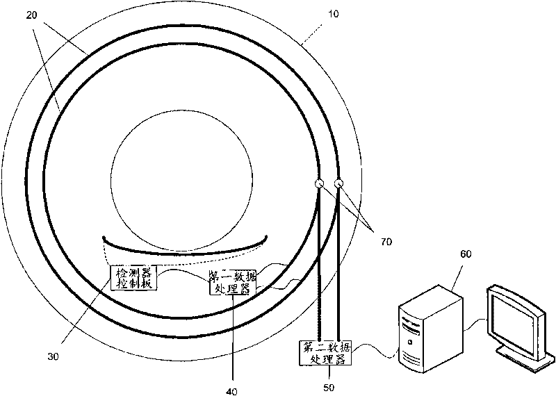
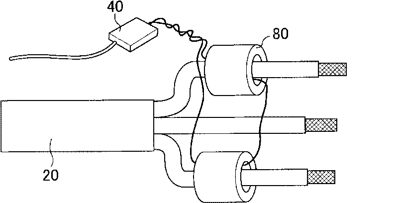
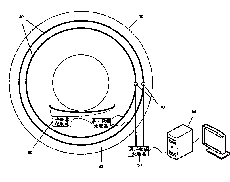
[0015] like figure 1 As shown, it is a schematic structural diagram of the CT scanning equipment of the present invention, including a scanning support 10, a power supply ring 20, a detector control board 30 for collecting scanning data signals from the detector, a first data processor 40, and a second data processor. 50 and a controller 60; wherein, the scanning support 10 includes a rotating part and a stationary part, and the power ring 20, the detector control board 30 and the first data processor 40 are set in the rotating part; the second data processor 50 is set in the rotating part. in the stationary part of the scanning gantry 10 . The detector control board 30 collects the scan data signals and transmits the collected scan data signals to the first data processor 40 through the da...


PUM


Abstract

The invention relates to CT scanning equipment comprising a scanning scaffold, a detector, a detector control board for controlling the detector and a power ring, wherein the scanning scaffold comprises a rotating part and a static part; the detector, the detector control board and the power ring are arranged in the rotating part; and the detector control board transmits scanning data signals collected on the detector to the static part from the rotating part of the scanning scaffold by a power line on the power ring, wherein the scanning equipment also comprises a first data processor arranged in the rotating part of the scanning scaffold and a second data processor arranged in the static part of the scanning scaffold; the first data processor is connected between the detector control board and the power ring, and the scanning data signals transmitted by the detector control board are transmitted to the power line of the power ring; the second data processor is connected with the power line of the power ring by a connecting brush, and the scanning data signals are transmitted to the second data processor of the static part from the rotating part of the scanning scaffold by the connecting brush. In the invention, the scanning data signals are transmitted to the static part from the rotating part of the scanning scaffold by the traditional power line, and a slide ring is not additionally arranged, thereby simplifying transmission paths and reducing the cost.

Description

technical field [0001] The present invention relates to a medical device technology, in particular to a computed tomography (CT) scanning device. Background technique [0002] The CT scanning equipment includes a scanning support and X-ray generators and detectors arranged in the scanning support. After the scan data collected from the detector is processed, it must be transferred from the rotating part of the scan gantry to the stationary part of the scan gantry for further data processing or display on a display. In CT scanning equipment, data transmission between the rotating part and the stationary part of the scanning gantry is a technical problem to be solved by all CT scanning equipment. In the prior art, the data transmission between the rotating part and the stationary part of the scanning bracket is established by adding another slip ring and setting a contact point on the slip ring; this technical solution can only guarantee to a certain extent. Reliable data tr...

Claims


Application Information

Patent Timeline
Patent Type & Authority Applications(China)
IPC IPC(8): A61B6/03
CPCA61B6/56
Inventor 孟达壮
Owner GE MEDICAL SYST GLOBAL TECH CO LLC
Why Eureka
Try Eureka