
Apparatus and method for pulling out valve cup ring

A pull-out device and valve seat ring technology, used in power tools, hand-held tools, manufacturing tools, etc., can solve problems such as incorrect engagement, damage to the valve seat ring and the pull-out device, and inappropriateness.

Active Publication Date: 2014-08-20
MAN ENERGY SOLUTIONS SA
View PDF4 Cites 0 Cited by
  • Summary
  • Abstract
  • Description
  • Claims
  • Application Information

AI Technical Summary

Problems solved by technology

[0004] In such manual pull-out devices, in which the seat ring is pulled out using hand force (Handkraft), it is generally not possible to apply high or defined pull-out forces.
In addition, due to the pivoting expansion claws in engagement with the seat ring, there is the risk of incorrect engagement, in particular a deflection of the expansion claws on the seat ring, which leads to a dislocation between the expansion claws and the seat ring. excessive wear and tear
Furthermore, unfavorable leverage ratios lead to high moment loads of the known pull-out devices
Here it is even possible to damage the seat ring and the pull-out device

Method used


Image

  • Apparatus and method for pulling out valve cup ring
  • Apparatus and method for pulling out valve cup ring
  • Apparatus and method for pulling out valve cup ring

Examples


Embodiment Construction

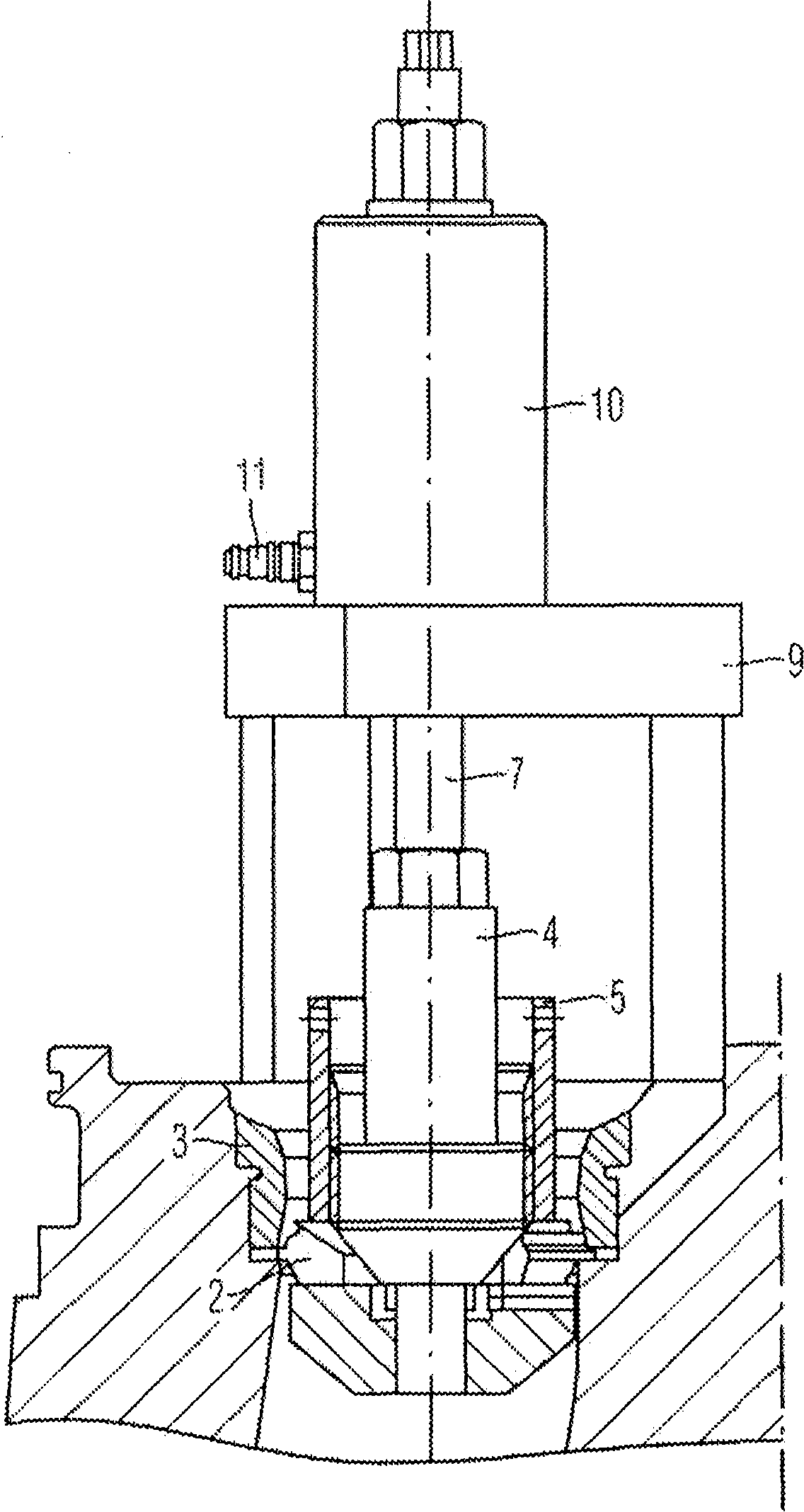
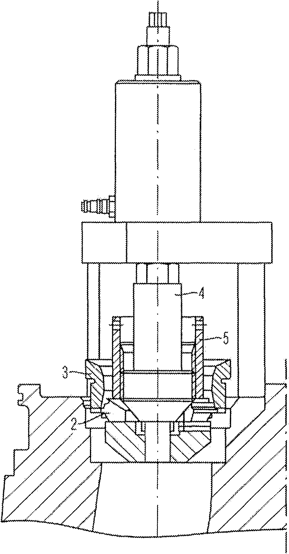
[0051] exist figure 1 In a perspective view, the drawing rod 7 of a drawing device according to an embodiment of the invention is shown, with three spreading claws 2 movably supported there, which can be screwed in by means of the cone 4 Move radially outward. The threaded sleeve 5 is used for locking, that is to say the fixing of the expansion jaw 2 (if the threaded sleeve 5 is screwed against the expansion jaw 2 on the pull-out rod 7 ). For a more detailed explanation, first refer to image 3 .

[0052] The figure shows in its right partial section a valve seat ring 3 , which is secured in a friction fit in a valve seat 12 of an intake valve of an internal combustion engine under preload. Likewise, a seat ring may be arranged in the exhaust valve.

[0053] According to one embodiment of the invention, the pull-out device is mounted on the valve seat. For this, as in image 3 Shown in the section on the right part of the gantry-shaped support part 9 from the field, that...


PUM


Abstract

The invention relates to a device and a method for pulling out a valve seat ring, in particular, in order to pull out a valve seat ring (3) from a valve seat (12) by means of a pulling device, a pull-out rod (7) is introduced into In the seat ring, the expansion claw (2) is brought into engagement with the seat ring and locked; and, an axial pulling force is applied to the pull-out rod in the pull-out direction by the hydraulic device (10), thereby , pull the seat ring out of its seat in the pull-out direction.

Description

technical field [0001] The invention relates to a pulling device (Ausziehvorrichtung) for a valve seat ring (Ventilsitzring) and a method for pulling out a valve seat ring by means of such a pulling device with a Pull-out lever (Ausziehspindel) in the seat ring with expansion jaw assembly (Spreizklauenanordnung) with expansion jaws that can be brought into engagement (Eingriff) with the seat ring Dynamically supported on the pull-out rod. Background technique [0002] Especially in order to ensure better sealing, but also to protect valves and valve seats against wear, it is known especially in larger internal combustion engines, such as large diesel engines and marine diesel engines, to provide separate valve seats in the valve seats A ring, for example made of a harder and / or more temperature-resistant material. Such a seat ring can, for example, be shrink-fitted onto the valve seat in a thermal manner, ie, temporarily cooling the ring and / or heating the seat, so that th...

Claims


Application Information

Patent Timeline
Patent Type & Authority Patents(China)
IPC IPC(8): B25B27/06B25B28/00
CPCB25B27/064B25B27/20B25B28/00B25B27/02B25B27/14
Inventor W·米彻勒M·瓦伦塔
Owner MAN ENERGY SOLUTIONS SA
Learn More