
CNC key tooth flower automatic punching machine

A punching machine and key technology, which is applied in the field of automatic punching machines for CNC key teeth, can solve the problems of not easy to ensure the key is clamped in place, inaccurate angle of reverse reset, affecting the quality of key teeth, etc. The effect of discharging, ensuring accuracy, and reducing space

Active Publication Date: 2017-04-19
HANGZHOU XINZHIYUAN CNC EQUIP
View PDF1 Cites 0 Cited by
  • Summary
  • Abstract
  • Description
  • Claims
  • Application Information

AI Technical Summary

Problems solved by technology

In this invention patent, the entire key tooth pattern is processed, the feeding cylinder drives the pusher plate back to the original position, the punching needle pushes the cylinder to drive the punching needle back to the original position, the positioning cylinder is released, and the pressing cylinder is released. Under the action of the small spring, the gap between the fixed key panel and the fixed key bottom plate is enlarged, and the Z-axis stepping motor drives the Z-axis from the synchronous wheel to a certain angle test, and the processed key falls out, which can be seen in the process of key tooth flower processing , It is troublesome to clamp the key. It needs the joint action of the positioning cylinder and the pressing cylinder. Not only the control cost is high, but also it is not easy to ensure that the key is clamped in place. When the key tooth flower needs to be discharged after the processing is completed, it must rely on the stepping motor to drive the synchronization. The wheel rotates, and then the key automatically falls under the action of gravity. It also requires higher requirements in terms of control, and after the key is dropped, the synchronous wheel has to be reversed and reset. After long-term use, the angle of reverse reset is easy. Inaccurate, it will affect the quality of subsequent key teeth

Method used


Image

  • CNC key tooth flower automatic punching machine
  • CNC key tooth flower automatic punching machine
  • CNC key tooth flower automatic punching machine

Examples


Embodiment Construction

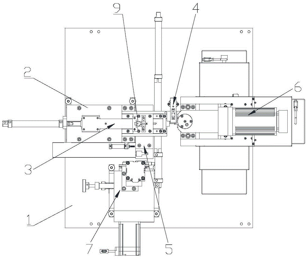
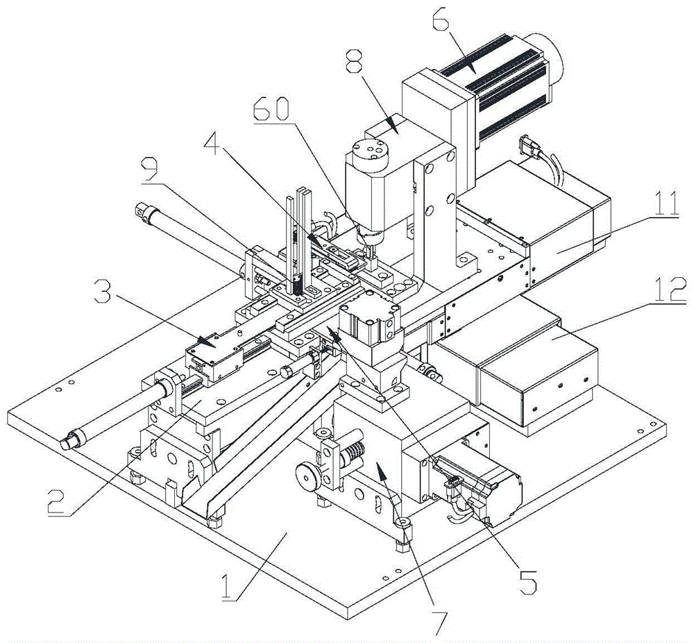
[0047] The present invention provides a kind of digital control key tooth flower automatic punching machine, such as figure 1 and figure 2 As shown, it includes a frame 1, a feeding mechanism and a tooth punching mechanism. The feeding mechanism includes a first bracket 2, a feeding assembly 3, a clamping assembly 4 and a discharging assembly 5. The first bracket 2 is installed on the frame 1, and the clamping The tightening assembly 4 is fixed on the front end of the first bracket 2, the discharge assembly 5 is arranged on the first bracket 2 and is located behind the clamping assembly 4, and the feeding assembly 3 drives the key 9 to be processed from the back to the front relative to the first bracket 2 To the clamping assembly 4, and drive the processed key 9 from front to rear relative to the first bracket 2 to the discharge assembly 5, the punching mechanism includes a drive assembly 6 and a punching knife 60, and the drive assembly 6 is installed through the feed carri...


PUM

PropertyMeasurementUnit
thicknessaaaaaaaaaa

Abstract

The invention discloses a numerical control automatic punching machine for key bits, belongs to the field of key machining machinery, and solves the problems of high control cost and inaccurate clamping in the prior art. According to the technical scheme, the numerical control automatic punching machine mainly comprises a rack, a feeding mechanism, and a punching mechanism, the feeding mechanism comprises a first support, a feeding assembly, a clamping assembly, and a discharging assembly, the first support is arranged on the rack, the clamping assembly is fixed at the front end of the first support, the discharging assembly is arranged on the first support and positioned at the back of the clamping assembly, the feeding assembly drives a to-be-machined key to the clamping assembly from the back to the front relative to the first support and drives the machined key to the discharging assembly from the front to the back relative to the first support, the punching mechanism comprises a driving assembly and a punching knife, the driving assembly is arranged above the rack via a feeding carriage, and the punching knife is positioned at the front of the first support and corresponds to the key clamped by the clamping assembly. The numerical control automatic punching machine is mainly used for machining the key bits.

Description

technical field [0001] The invention relates to a key processing machine, in particular to a numerically controlled key tooth punching machine. Background technique [0002] Limited to the material of the key, generally copper and aluminum keys are processed by milling machines, while iron keys are processed by punching machines. For example, the utility model patent with the authorized announcement number CN202097323U discloses a processing device for punching key teeth with numerical control, including a feeding mechanism, a clamping mechanism, a tooth punching mechanism, a bottom plate and a panel, and the clamping mechanism is arranged at the front end of the feeding mechanism. The punching mechanism corresponds to the clamping mechanism; the clamping mechanism is composed of a fixed key mechanism and a transmission mechanism that drives the fixed key mechanism to rotate and translate; the fixed key mechanism includes a fixed key panel and a fixed key bottom plate, a fix...

Claims


Application Information

Patent Timeline
Patent Type & Authority Patents(China)
IPC IPC(8): B21D53/42B21D43/02
CPCB21D28/04B21D43/04B21D53/42
Inventor 甄健松
Owner HANGZHOU XINZHIYUAN CNC EQUIP
Learn More