Rear power takeoff for speed changing box

A technology of gearbox and power take-off, applied in the direction of gear transmission, gear lubrication/cooling, belt/chain/gear, etc. The effect of improving the force condition and the compact structure in the axial direction

Active Publication Date: 2012-11-21
DONGFENG MOTOR CORP HUBEI
View PDF0 Cites 0 Cited by
  • Summary
  • Abstract
  • Description
  • Claims
  • Application Information

AI Technical Summary

Problems solved by technology

[0002] At present, the rear power take-off for the gearbox is installed on the rear side of the gearbox. The support structure of the output shaft is a cantilever support with two support bearings arranged in the casing near the output end. The output shaft is not supported near the drive shaft end. This structure The force on the output shaft is not uniform during the force taking process; at the same time, the shell adopts an integral shell, which requires the output shaft to be relatively long to ensure the installation and connection of the output shaft and the shell
Therefore, the structure volume of the rear power take-off of the above-mentioned gearbox is relatively large, and the structure of the clutch driving device in the housing is relatively large, which increases the cost of parts and is not convenient for the arrangement of other power devices on the chassis of a special vehicle; at the same time, the cantilever support structure of the output shaft causes the output The clutch section of the shaft is easy to wear, and after a long time of use, it is difficult to ensure the coaxiality of the output shaft and the power take-off gear shaft

Method used


Image

  • Rear power takeoff for speed changing box
  • Rear power takeoff for speed changing box

Examples


Embodiment 2

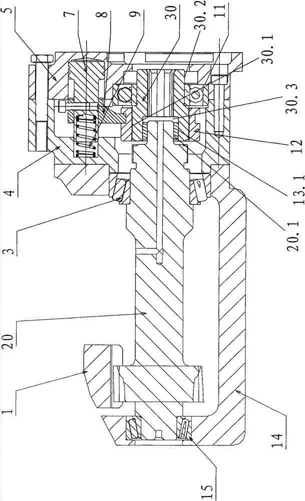
[0026] It has some structural differences with the embodiment, such as figure 2 As shown, the power take-off gear shaft 20 in this embodiment has at least 6 sections, that is, the support section 20.1 connected with the output shaft 30 is added on the basis of the five sections of Embodiment 1. The output shaft 30 in this embodiment is at least composed of Two sections, that is, only the spline section 30.1 and the support section 30.2 connected by the clutch spline sleeve, the spline section 30.1 is provided with a connection support hole 30.3 at the end, and the support section 20.1 of the power take-off gear shaft 20 extends into the connection In the support hole 30.3, a bearing 13.1 is provided between the support section 20.1 and the connecting support hole 30.3, so as to support the output shaft 30. Other structures of the power take-off in this embodiment are the same as those of the power take-off in Embodiment 1, and will not be repeated here.


PUM


Abstract

The invention discloses a rear power takeoff for a speed changing box, which comprises a power takeoff gear shaft, wherein one end of the power takeoff gear shaft is provided with a spline section and an output shaft being in coaxial on-off with the power takeoff gear shaft, a shaft circle at one end of the output shaft is provided with a spline section corresponding to the spline section on the power takeoff gear shaft, the spline section of the output shaft is connected with a clutch spline sleeve which is connected with a clutch drive device, and the other end of the output shaft is provided with an output connecting spline hole. The rear power takeoff also comprises a front shell and a rear shell which are connected mutually, the shaft end of the power takeoff gear shaft is provided with a connecting supporting hole, the end part of the output shaft is supported in the connecting supporting hole at the shaft end of the power takeoff gear shaft through a bearing, and the other end of the output shaft is supported between the front shell and the rear shell. The rear power takeoff has compact axial structure and small volume, and can be widely applied to medium and heavy speed changing boxes.

Description

technical field [0001] The invention belongs to a power take-off, in particular to a power take-off after a gearbox connected with a gearbox. Background technique [0002] At present, the rear power take-off for the gearbox is installed on the rear side of the gearbox. The support structure of the output shaft is a cantilever support with two support bearings arranged in the casing near the output end. The output shaft is not supported near the drive shaft end. This structure The output shaft is subjected to uneven force during the force taking process; meanwhile, the housing adopts an integral housing, which requires the output shaft to be relatively long to ensure the installation and connection of the output shaft and the housing. Therefore, the structure volume of the rear power take-off of the above-mentioned gearbox is relatively large, and the structure of the clutch driving device in the housing is relatively large, which increases the cost of parts and is not conven...

Claims


Application Information

Patent Timeline
Patent Type & Authority Patents(China)
IPC IPC(8): B60K25/06F16H3/083F16H57/04
Inventor 文世红杨立斌邬丽萍刘玉祥吕鉴福李苏稳
Owner DONGFENG MOTOR CORP HUBEI
Why Eureka
Try Eureka