Rotating gas-jetting rotor

A technology for rotating jets and rotors, which is used in jet propulsion devices, gas turbine devices, and air inlets of turbine/propulsion devices. and other problems, to achieve the effect of good dynamic balance performance, compact axial structure and large output torque

Active Publication Date: 2019-01-04
ANHUI UNIVERSITY OF TECHNOLOGY
View PDF6 Cites 0 Cited by
  • Summary
  • Abstract
  • Description
  • Claims
  • Application Information

AI Technical Summary

Problems solved by technology

However, the existing jet engines cannot be directly applied to rotorcraft, such as saucer-shaped aircraft, because the rotorcraft requires a large output torque, and has the characteristics of high power-to-weight ratio and small axial structure size

Method used


Image

  • Rotating gas-jetting rotor
  • Rotating gas-jetting rotor
  • Rotating gas-jetting rotor

Examples


Embodiment Construction

[0018] The present invention will be described in detail below in conjunction with the accompanying drawings and specific embodiments, but the present invention is not limited to the following embodiments.

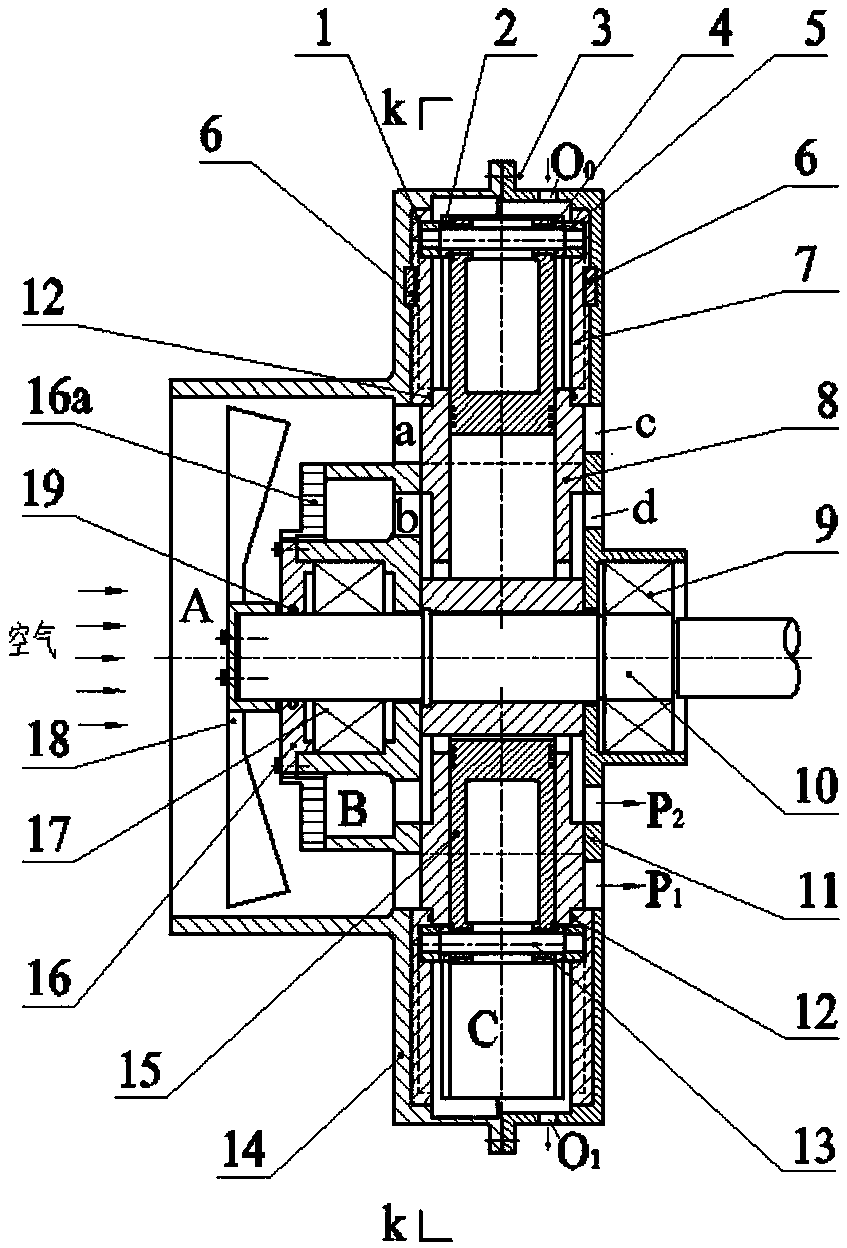
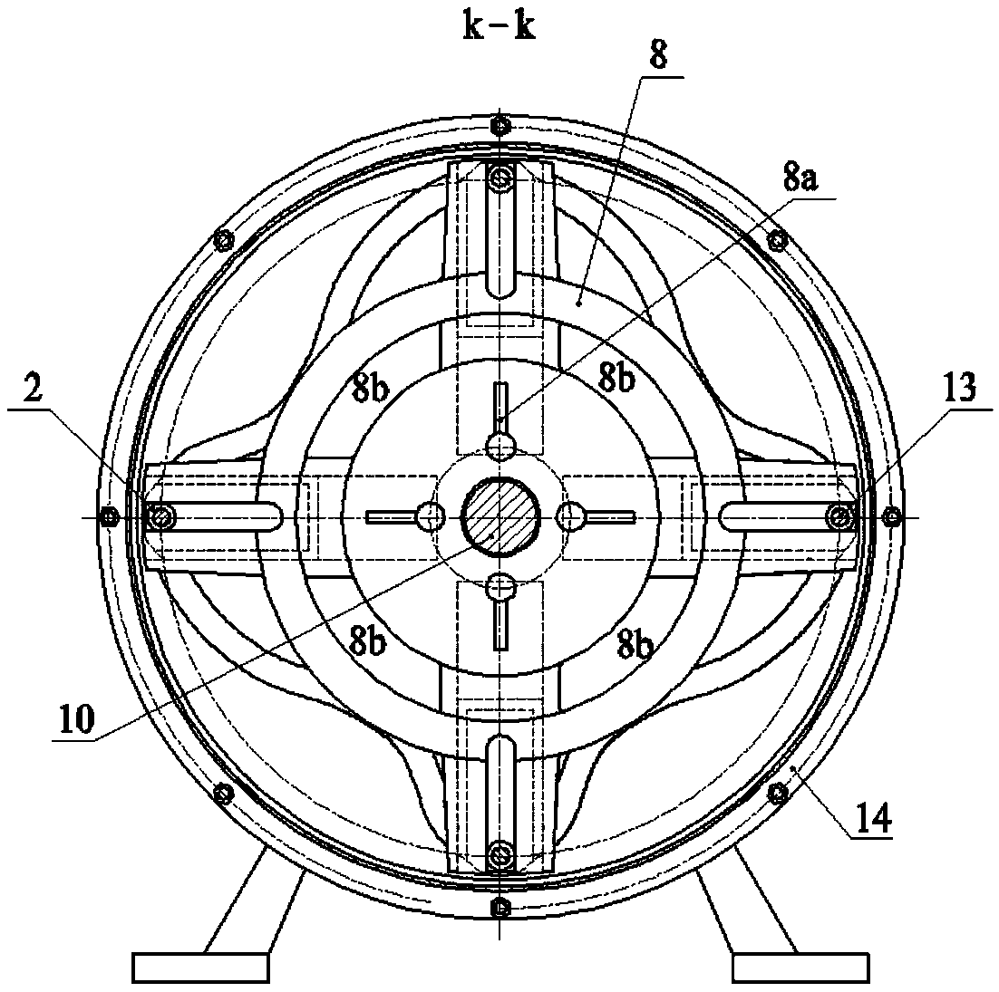
[0019] exist figure 1 Among them, the central shaft 2 sequentially passes through the inner hole of the bearing 3 and the turntable 6 and is axially fixed by the round nut group 7 (including the round nut and the stop washer), wherein the inner ring of the bearing 3 is positioned by the shoulder of the central shaft 2, and the turntable The end surface of the inner hole of 6 is in contact with the end surface of the inner ring of the bearing 3; a key 9 is installed between the central shaft 2 and the turntable 6 for circumferential positioning. Two spark plugs 12 are symmetrical to the axis of the turntable, and are fixedly installed on the right side wall of the main combustion chamber 6d through threaded connection. The valve core 13, spring 14 and guide tube 4 are seque...


PUM


Abstract

The invention discloses a rotating gas-jetting rotor, and belongs to the technical field of jet engine equipment. The rotating gas-jetting rotor comprises a box, a box cover, a center shaft, a rotating disc, a conductive ring, a spark plug, a flow guiding pipe, a valve core and a spring; the box and the box cover are fixedly connected to form a machine base, the conductive ring is fixedly connected with the box cover, the center shaft and the rotating disc are fixedly connected to form an axisymmetric rotating body, and the rotating disc is provided with a main combustion chamber and a C-shaped gas channel; and high-pressure mixed gas enters the main combustion chamber, high-pressure gas generated by ignition combustion of the spark plug is jet from the front end of the valve core to be mixed or combusted with air sucked by the flow guiding pipe or combustible mixed gas in the C-shaped gas channel to form high-energy gas, the gas is jet from a spraying nozzle on the rotating disc to generate thrust, the rotating body is pushed to rotate at the high speed, and rotating moment is output. The rotating gas-jetting rotor has the characteristics that output power and the self-weight ratio are large, the axial structure is compact, the manufacturing cost is low, and dynamic balance performance is good.

Description

technical field [0001] The invention belongs to the technical field of jet engine equipment, and in particular relates to a rotating jet rotor. Background technique [0002] The jet engine is usually the power equipment of the aircraft. It can use the high-speed flying airflow to enter the static combustion chamber of the engine to generate a large amount of high-pressure airflow and inject it backward from the tail nozzle to generate thrust. It has the advantages of compact structure, large thrust-to-weight ratio, stable thrust and easy control. It is widely used in high-speed automobiles, aircrafts, missiles and other fields. However, existing jet engines cannot be directly applied to rotorcraft, such as saucer-shaped aircraft, because the rotorcraft requires high output torque, and has the characteristics of high power-to-weight ratio and small axial structure size. Contents of the invention [0003] Aiming at the deficiencies of the existing jet engines, the present i...

Claims


Application Information

Patent Timeline
Patent Type & Authority Applications(China)
IPC IPC(8): F02K1/00F02C7/266F02C7/04
CPCF02C7/04F02C7/266F02K1/00
Inventor 张玉华张维王孝义
Owner ANHUI UNIVERSITY OF TECHNOLOGY
Why Eureka
Try Eureka