A magnetorheological fluid transmission device of high-temperature gear variable multi-face

A magneto-rheological fluid and multi-working surface technology, which is applied in fluid transmission devices, transmission devices, belts/chains/gears, etc., can solve problems such as increasing contact area, reducing transmission torque, and poor torque transmission stability , to achieve the effect of good torque stability, guaranteed torque size and simple structure

Inactive Publication Date: 2020-12-08
CHONGQING UNIV OF TECH
View PDF2 Cites 0 Cited by
  • Summary
  • Abstract
  • Description
  • Claims
  • Application Information

AI Technical Summary

Problems solved by technology

[0005] In view of the above-mentioned deficiencies in the prior art, the purpose of the present invention is to solve the problem of the reduction of the transmission torque and the poor stability of torque transmission with the increase of temperature, and provide a high-temperature gear variable multi-face magneto-rheological The hydraulic transmission device can automatically increase the contact area between the magneto-rheological fluid and the main and driven parts after the temperature rises, thereby compensating for the torque reduced due to the decrease of the magneto-rheological effect, thereby ensuring the transmission of the transmission device. The size of the torque and make the torque transmission of the transmission device more stable

Method used


Image

  • A magnetorheological fluid transmission device of high-temperature gear variable multi-face
  • A magnetorheological fluid transmission device of high-temperature gear variable multi-face
  • A magnetorheological fluid transmission device of high-temperature gear variable multi-face

Examples


Embodiment

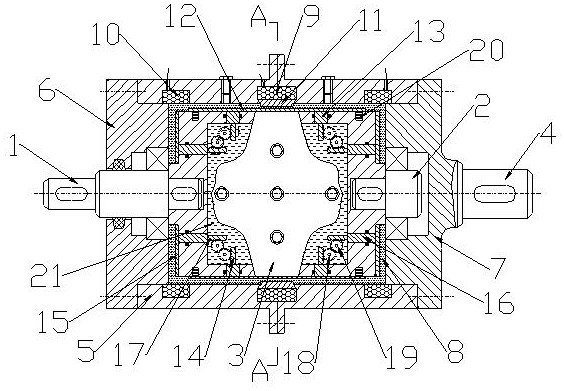
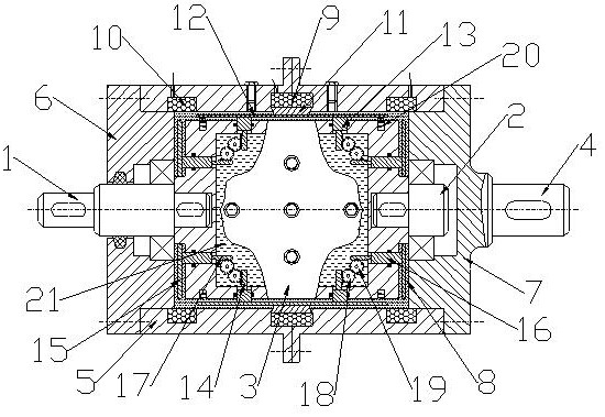
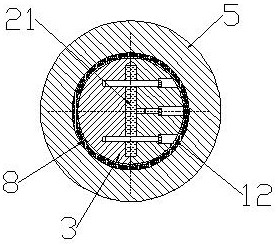
[0022] Example: see figure 1 , figure 2 as well as image 3 , a magneto-rheological fluid transmission device of high-temperature gear variable multi-face, including a left driving shaft 1, a right driving shaft 2, a driving inner cylinder 3, a driven shaft 4, a driven outer cylinder 5, and a left end cover 6 and Right end cap 7. Wherein, the right end cover 7 is formed by expanding the left end of the driven shaft 4; the left end cover 6 and the right end cover 7 are fixedly connected with the left and right ends of the driven outer cylinder 5 respectively. The two ends of the active inner cylinder 3 are closed structures; the right end of the left drive shaft 1 passes through the left end cover 6 and is fixedly connected with the left end of the active inner cylinder 3, and is connected with the left end cover 6 through a bearing, and the right drive shaft 2 The left end of the left end is fixedly connected with the right end of the driving inner cylinder 3, and is conne...


PUM


Abstract

The invention discloses a high-temperature tooth-type working-area-increasing magnetorheological fluid transmission device. The high-temperature tooth-type working-area-increasing magnetorheological fluid transmission device comprises a left driving shaft, a right driving shaft, a driving inner cylinder, a driven shaft, a driven outer cylinder, a left end cover and a right end cover, wherein magnetorheological fluid fills in a space among the driving inner cylinder, the left end cover, the driven outer cylinder and the right end cover; a plurality of radial pressing discs are distributed on the outer side of the driving inner cylinder; radial guiding rods are disposed on the inner sides of the radial pressing discs and extend into the driving inner cylinder to be provided with radial racks; the two ends of the driving inner cylinder are sleeved with axial pressing discs correspondingly; axial guiding rods are disposed on one sides of the axial pressing discs and extend into the drivinginner cylinder to be provided with axial racks; and a plurality of shape memory alloy springs are disposed between the radial pressing discs and the driving inner cylinder. By means of the high-temperature tooth-type working-area-increasing magnetorheological fluid transmission device, after the temperature is increased, the contact area between the magnetorheological fluid and driving and drivenparts can be automatically increased, so that the torque reduced due to decrease of the magnetorheological effect is compensated.

Description

technical field [0001] The invention relates to a transmission device, in particular to a magneto-rheological fluid transmission device of a high-temperature tooth type variable multi-working face. Background technique [0002] Both magnetorheological fluid and shape memory alloy are new materials developed in modern times, and their properties and states can be changed by changing their external physical fields (such as magnetic field and temperature field); using the special properties of these two materials, in Increasing use in transmissions such as clutches; however, currently, magneto-rheological fluids and shape-memory alloy springs are mostly single-use: [0003] As disclosed in CN103603891A, the "multi-plate magnetorheological fluid electromagnetic clutch" utilizes a multi-plate structure and uses magnetorheological fluid as a medium to fill the gaps between a plurality of main and driven friction plates of the electromagnetic clutch to form multiple magnetic curren...

Claims


Application Information

Patent Timeline
Patent Type & Authority Patents(China)
IPC IPC(8): F16H47/06
CPCF16H47/06
Inventor 黄金王西
Owner CHONGQING UNIV OF TECH
Why Eureka
Try Eureka