Accelerated degradation test method of multistage separation type dynode electron multiplier

A technology of accelerated degradation test and electron multiplier, which is applied in the direction of radiation intensity measurement, etc., and can solve problems such as research reports on the accelerated degradation test method of electron multiplier that have not been seen.

Active Publication Date: 2010-06-23
NAT UNIV OF DEFENSE TECH
View PDF0 Cites 8 Cited by
  • Summary
  • Abstract
  • Description
  • Claims
  • Application Information

AI Technical Summary

Problems solved by technology

At present, the accelerated degradation test has been applied in the performance degradation life prediction of light-emitting diodes, logic integrated circuits, power supplies, insulators, and pharmaceuticals, but there is no research report on the accelerated degradation test method of electron multipliers.

Method used


Image

  • Accelerated degradation test method of multistage separation type dynode electron multiplier
  • Accelerated degradation test method of multistage separation type dynode electron multiplier
  • Accelerated degradation test method of multistage separation type dynode electron multiplier

Examples


Embodiment Construction

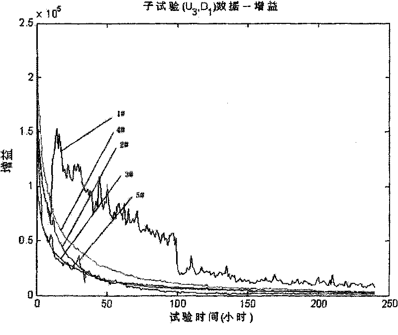
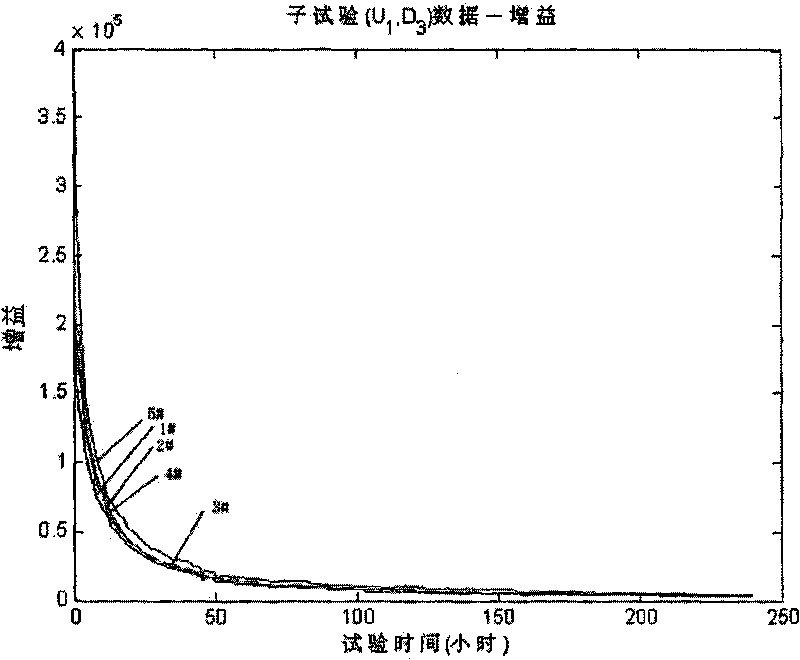
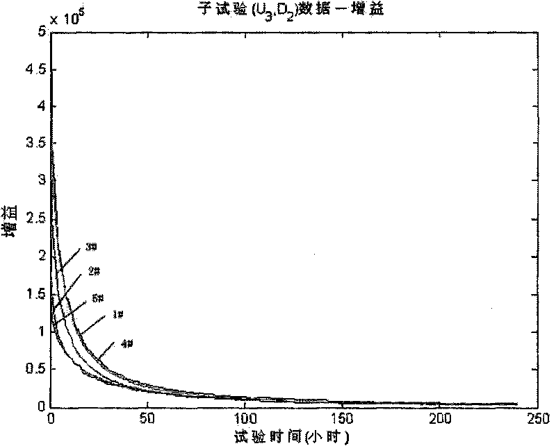
[0053] The specific implementation of the method of the present invention will be further described below by taking a domestic 9-stage separated dynode electron multiplier as an example. The cathode and each dynode material of the electron multiplier are Mg-AgO alloy, using CO 2 The activation mode is used for cesium ion beam detection and intensity amplification in an atomic frequency standard system. It should be pointed out that the following implementations are only used to illustrate the present invention, but not to limit the scope of the present invention.

[0054] Example 1 , 9-stage separated dynode electron multiplier accelerated degradation test

[0055] Step 1. Put the electron multiplier sample into a sealed container with multiple terminals, connect the electrodes of the electron multiplier to the corresponding terminals, pump and maintain the vacuum in the sealed container. Five electron multiplier samples are put into each round of test, and each electron m...


PUM


Abstract

The invention discloses an accelerated degradation test method of a multistage separation type dynode electron multiplier, which comprises the following steps: 1) placing at least five electron multiplier samples in a sealed container with binding posts, connecting electrodes of the electron multipliers with the corresponding binding posts, pumping the sealed container and maintaining vacuum; 2) respectively imposing at least three groups of incident particle flow strengths and working voltage values with different levels but higher than the normal using level on all the electron multiplier samples; 3) utilizing a milli-ampere current meter for carrying out continuous monitoring on the output current of all the electron multipliers; dividing the output current by the incident particle flow strength, converting into gain data and recording; and 4) utilizing a computer for processing the recorded gain data of the electron multipliers, and obtaining the predicted result of the service life.

Description

technical field [0001] The invention belongs to the technical field of accelerated testing of electric vacuum devices, and in particular relates to a method for evaluating the electron multiplier by monitoring and analyzing the gain data information of a multi-stage separated dynode electron multiplier (hereinafter referred to as the electron multiplier) under accelerated conditions. An accelerated test method for the life time of the device under actual use conditions. Background technique [0002] Electron multipliers are vacuum electronic devices that are widely used in atomic frequency standards, low-light night vision, nuclear detection, mass spectrometry, medical X-ray imaging and other fields, and are the core basic devices that restrict the development of technologies in related fields. Electron multiplier life is usually defined as the working time when its gain drops to a certain threshold under normal working conditions, which is a typical performance degradation ...

Claims


Application Information

Patent Timeline
Patent Type & Authority Applications(China)
IPC IPC(8): G01T1/16
Inventor 张春华汪亚顺陈循陶俊勇莫永强邓爱民郑凯张国洪
Owner NAT UNIV OF DEFENSE TECH
Why Eureka
Try Eureka