
CQI estimation method, system and device during multi-stream beamforming transmission

A beamforming and estimation module technology, applied in transmission system, digital transmission system, diversity/multi-antenna system, etc., can solve problems such as inaccurate CQI

Active Publication Date: 2013-08-07
DATANG MOBILE COMM EQUIP CO LTD
View PDF0 Cites 0 Cited by
  • Summary
  • Abstract
  • Description
  • Claims
  • Application Information

AI Technical Summary

Problems solved by technology

[0005] The purpose of the present invention is to at least solve one of the above-mentioned technical defects, especially solve the defect that the CQI estimated by the base station is inaccurate during multi-stream beamforming transmission in the prior art

Method used


Image

  • CQI estimation method, system and device during multi-stream beamforming transmission
  • CQI estimation method, system and device during multi-stream beamforming transmission
  • CQI estimation method, system and device during multi-stream beamforming transmission

Examples


Embodiment Construction

[0027] Embodiments of the present invention are described in detail below, examples of which are shown in the drawings, wherein the same or similar reference numerals designate the same or similar elements or elements having the same or similar functions throughout. The embodiments described below by referring to the figures are exemplary only for explaining the present invention and should not be construed as limiting the present invention.

[0028] The present invention mainly lies in compensating the CQI fed back by the UE through the uplink channel information matrix estimated by the base station from the uplink sounding pilot signal sent by the UE, so that the base station can obtain the actual CQI of each beamforming data stream.

[0029] In order to have a clear understanding of the present invention, a brief introduction to multi-stream beamforming transmission is given below. Since there is no specific regulation in the LTE standard at present, the following multi-str...


PUM


Abstract

The invention provides a channel quality indicator CQI estimation method during multi-stream beamforming transmission, which comprises the following steps: a base station receives a CQI which is fed back by an user equipment UE and estimated by the UE according to a signal of a common pilot port indicated by broadcast information; the base station estimates uplink channel information according toan uplink detection signal sent by the UE; and the base station obtains the actual CQI of each beamforming data stream according to the CQI fed back by the UE and the estimated uplink channel information. The base station can estimate the reasonable CQI during the multi-stream beamforming transmission by adopting the method, thereby being conductive to leading the base station to select the appropriate MCS for the UE and further ensure the normal data transmission.

Description

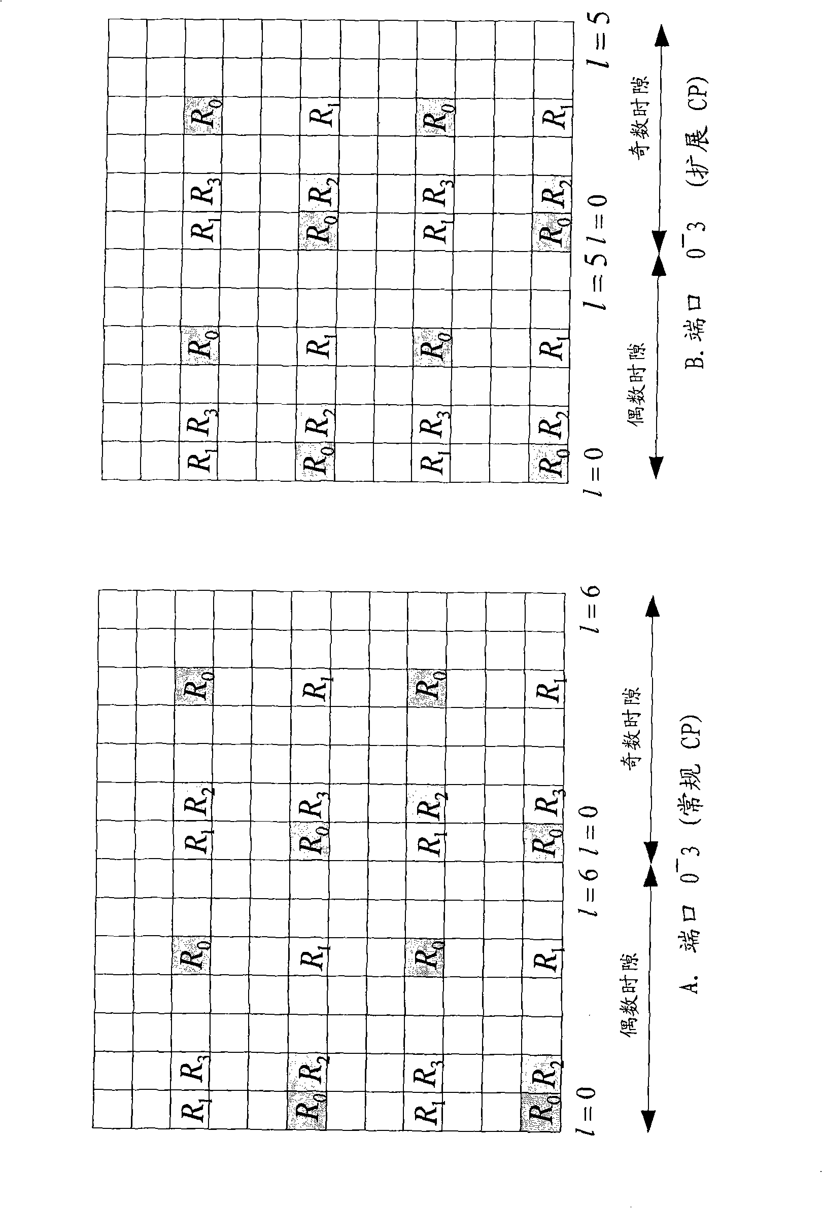
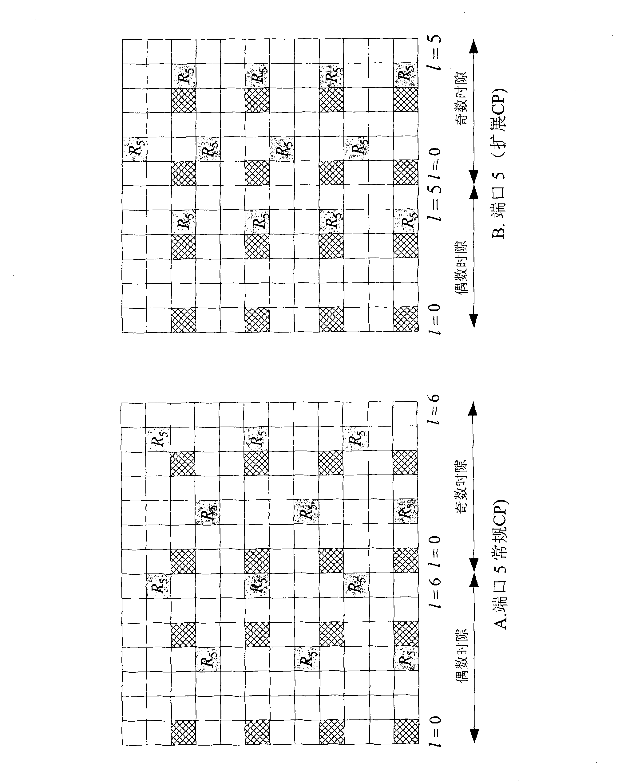
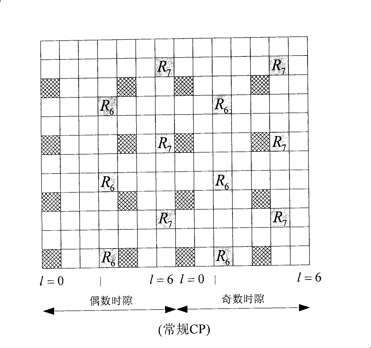
technical field [0001] The present invention relates to the technical field of mobile communication, in particular to a CQI (Channel Quality Indicator, Channel Quality Indicator) estimation method, system and device during multi-stream beamforming transmission. Background technique [0002] In the LTE (Long Term Evolution, long-term evolution) system, the common pilot is common to the cell, and there are currently 4 ports of the common pilot signal, such as figure 1 As shown, it is a schematic diagram of LTE system common pilot mapping in the prior art, which is sent on the full bandwidth. The dedicated pilot is based on UE (User Equipment, user equipment), that is, each user can only receive its own dedicated pilot signal. In the LTE-R8 system, the port number of the dedicated pilot is 5, such as figure 2 As shown, it is a schematic diagram of dedicated pilot mapping in the prior art, and the time-frequency resource occupied by the dedicated pilot does not conflict with ...

Claims


Application Information

Patent Timeline
Patent Type & Authority Patents(China)
IPC IPC(8): H04B7/04H04L1/00
Inventor 孙韶辉缪德山秦飞
Owner DATANG MOBILE COMM EQUIP CO LTD
Learn More