
Device for fixing electrical mechanism on frame base

A frame and electrical technology, applied in the installation of electrical components, coupling devices, support structures, etc., can solve the problems of increased cost and increased installation time

Inactive Publication Date: 2010-06-23
SIMON SA
View PDF5 Cites 7 Cited by
  • Summary
  • Abstract
  • Description
  • Claims
  • Application Information

AI Technical Summary

Problems solved by technology

[0002] The operation of fixing said electrical mechanism for various purposes, externally defined in a matrix, to the base of the frame, which must maintain its permanent position, must currently use a sufficient number of elements, such as screws, staples or other similar elements, due to Its manufacturing and labor, which cause an increase in cost, once these components are used, the installation time must also increase

Method used


Image

  • Device for fixing electrical mechanism on frame base
  • Device for fixing electrical mechanism on frame base
  • Device for fixing electrical mechanism on frame base

Examples


Embodiment Construction

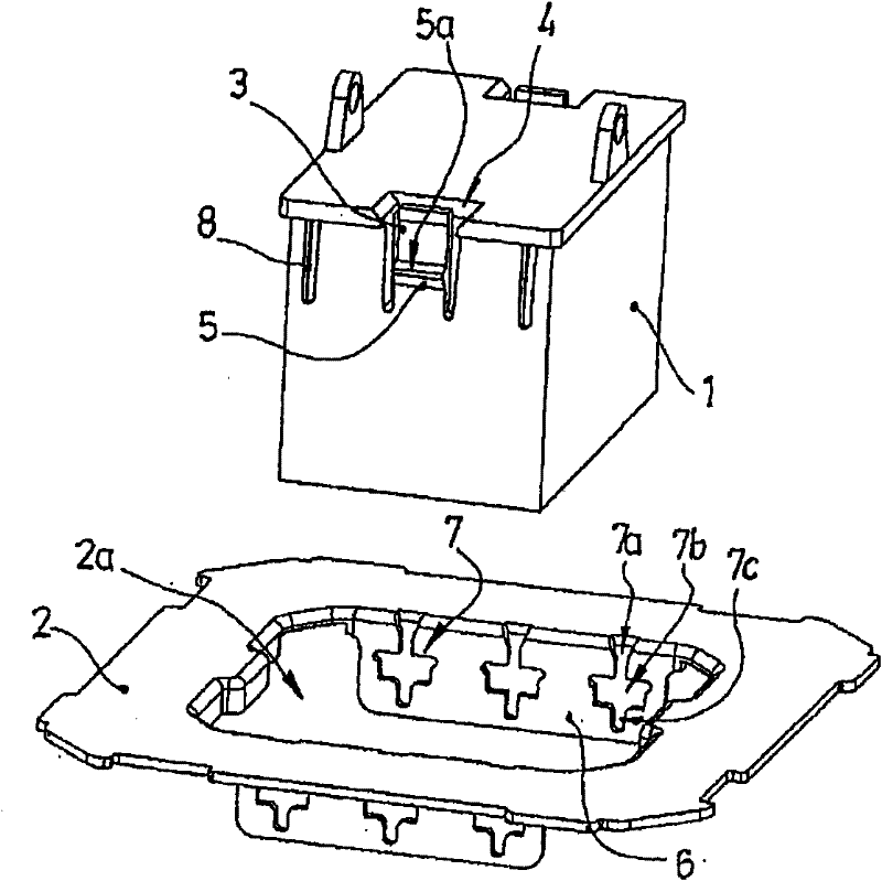
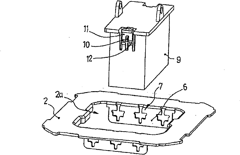
[0021] According to the drawings, the fixing device for the purpose of the present invention can be applied to various functional electrical mechanisms. These electrical mechanisms are integrated in the base 1. The fixing device can be directly fixed to the central opening 2a of the frame base 2 without any fixing, Connect or clamp accessories.

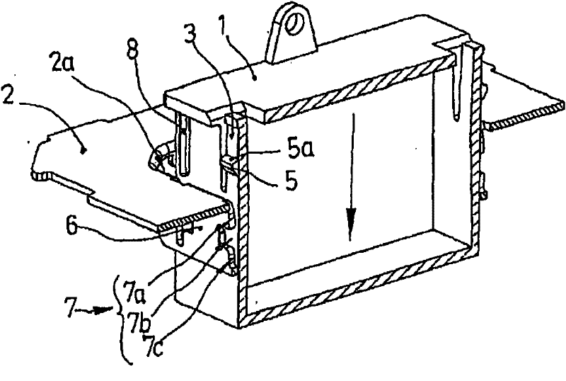
[0022] An important feature of the device that is the object of the present invention is that once the base 1 is set in the central opening 2a of the frame base 2, it can be fixed in the aforementioned central opening 2a of the frame base 2, without swinging in the front-to-rear direction, nor Will move sideways in the horizontal direction.

[0023] When the base body is set in its installation position, due to the two vertical guide flanges 8 symmetrically arranged on each front side of the base body 1, the sliding of the base body 1 into the central opening 2a can be guided and thus centered. .

[0024] These vertical guide flanges 8 are...


PUM


Abstract

A basal body (1) is provided with two vertical guide flanges (8) symmetrically on its two side faces, the vertical guide flanges (8) face to corresponding grooves (7) arranged on a vertical surface (6) of a frame base (2), and the flanges (8) slide into the grooves (7) during a process that the basal body (1) moves to be located in the frame base (2) finally, so as to prevent the basal body (1) from swinging or laterally moving. Each groove (7) has a special contour for limiting an upper area (7a), a wide central area (7b) and a straight lower area (7c), and the upper area (7a) is slightly spreaded out and reaches the edge of the frame base (2). A tongue (3) faces to the central groove (7), a nip part (5) reaches the edge of the frame base (2), the nip part (5) is pressed, such that the tongue is pressed and moves toward the inner of the basal body (1) due to flexibility, when the basal body (1) reaches a final position and the nip part (5) is guided into the wide area (7b) of the groove (7) so as to be fastened mutually, and the tongue returns to the original position. A basal body (9) with a smaller width is provided with a single vertical guide flange (10).

Description

Technical field [0001] The present invention relates to a device for fixing an electric mechanism to a frame base. The electric mechanism includes a base body and is integrated in the base body. The frame base is used to position and unsuitably position the mechanism. Permanently installed in the corresponding box or enclosure, the important features of the device are as follows. Background technique [0002] The operation of fixing the electric mechanism for various purposes externally confined in the base body to the frame base that must maintain its permanent position must currently use enough elements, such as screws, staples or other similar elements, because The manufacturing and labor cost increases. Once these components are used, the installation time will inevitably increase. Summary of the invention [0003] The fixing device, which is the object of the present invention, provides a practical and effective solution to the disadvantages of the prior art. It combines ver...

Claims


Application Information

Patent Timeline
IPC IPC(8): H05K7/14
CPCH01R13/743H02G3/123H02B1/048
Inventor M·C·莫雷特 考迪纳
Owner SIMON SA
Learn More