Roll mill

A rolling mill and grinding plate technology, which is applied in the direction of mechanical equipment, grain processing, belt/chain/gear, etc., can solve the problems of disturbing the grinding bed, unfavorable, disturbing the grinding process, etc.

Inactive Publication Date: 2010-06-23
KRUPP POLYSIUS AG
View PDF3 Cites 16 Cited by
  • Summary
  • Abstract
  • Description
  • Claims
  • Application Information

AI Technical Summary

Problems solved by technology

These are undesirable because they disturb the grinding process, especially the grinding bed, and thus adversely affect production capacity and energy consumption

Method used


Image

  • Roll mill
  • Roll mill
  • Roll mill

Examples


Embodiment Construction

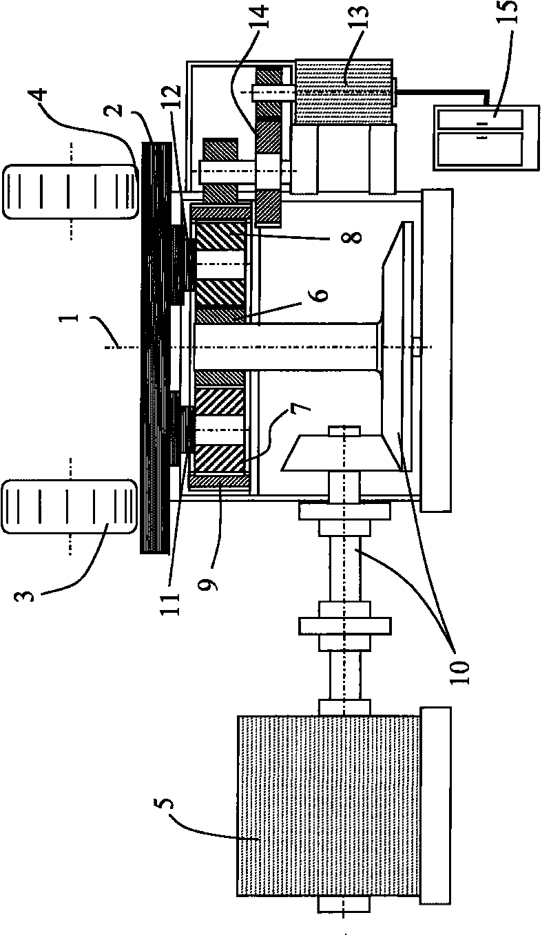
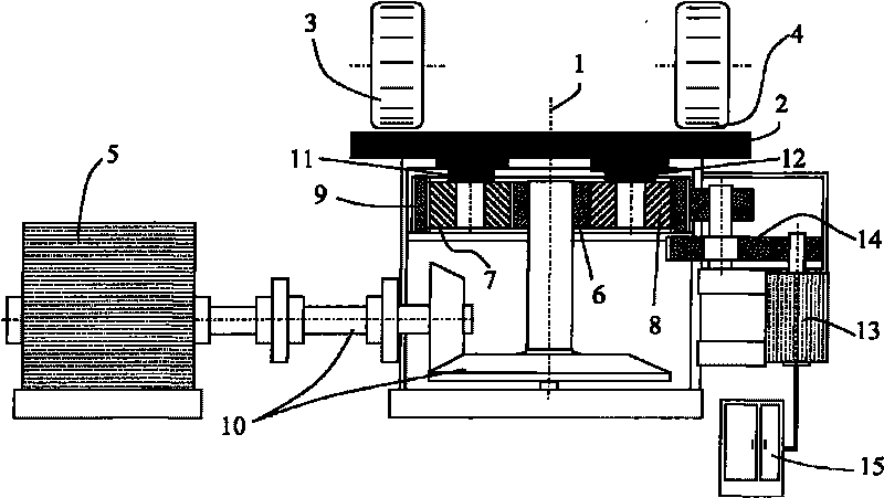
[0017] figure 1 The roller mill shown basically comprises a grinding plate 2 rotatable about an axis of rotation 1 , at least one grinding roller 3 , 4 in rolling engagement with said grinding plate, and a main drive system 5 for driving said grinding plate.

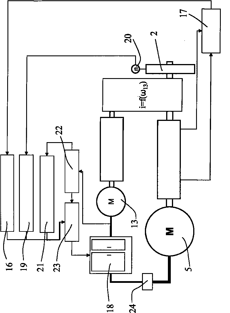
[0018] The main drive system 5 includes a planetary gear with a sun gear 6 , a plurality of planet gears 7 , 8 and a ring gear 9 . The main drive system 5 drives the sun gear 6 via the main drive 10 .

[0019] The planet wheels 7 , 8 are connected to the grinding plate 2 via planet carriers 11 , 12 such that the grinding plate can rotate about the axis of rotation 1 . In this arrangement, the axis of rotation 1 is oriented vertically.

[0020] Furthermore, an auxiliary drive system 13 is provided for driving the grinding plate 2 . To this end, the ring gear 9 of the planetary gear is rotatably arranged and connected to a secondary transmission 13 via a secondary transmission 14 .

[0021] The secondary drive system 1...


PUM


Abstract

The invention relates to a roll mill having a grinding plate (2) which can rotate about an axis (1) of rotation, at least one grinding roller (3, 4) which engages in a rolling manner with the grinding plate (2), and a main drive (5) for driving the grinding plate (2). Furthermore, an auxiliary drive (13) is provided for driving the grinding plate (2) and a regulating device (15), wherein the regulating device (15) has at least one damping regulator (16, 21) which regulates the auxiliary drive (13) according to torque variations of the main drive (5) and / or rotary speed variations of the grinding plate (2).

Description

technical field [0001] The invention relates to a rolling mill having a grinding plate rotatable about an axis of rotation, at least one grinding roller in rolling engagement with the grinding plate, and a main drive for driving the grinding plate. Background technique [0002] Currently, the grinding plates of vertical roller mills are driven by uncalibrated asynchronous or synchronous motors and multi-stage transmissions. With this arrangement, in practice, the grinding process results in large torque variations. Furthermore, these torque variations are exacerbated due to oscillating transmission systems (clutches, shafts, components with rigid teeth). A rolling mill is known, for example, from DE 36 33 747 A1. [0003] In order to be able to withstand these varying high loads, all components involved directly and / or indirectly in the transmission path must be specially designed. In particular, alternating stresses due to characteristic changes within the drive train ca...

Claims


Application Information

Patent Timeline
Patent Type & Authority Applications(China)
IPC IPC(8): B02C15/00B02C23/00F16H37/06
CPCB02C23/00B02C25/00B02C15/006
Inventor 马库斯·贝格尔佩德罗·格雷罗·帕尔马
Owner KRUPP POLYSIUS AG
Why Eureka
Try Eureka