Waist support device of electric driver seat

A lumbar support and seat technology, applied in chairs, other seating furniture, stools, etc., can solve the problems of inconvenient moving back and forth, poor cushioning performance of rigid body supports, etc., to ensure durability and reliability, and improve service life. , the effect of reducing wear

Inactive Publication Date: 2010-06-30
NORTHEASTERN UNIV
View PDF3 Cites 8 Cited by
  • Summary
  • Abstract
  • Description
  • Claims
  • Application Information

AI Technical Summary

Problems solved by technology

[0004] Aiming at the problem that the elastic body support in the existing seat lumbar support device is inconvenient to move back and forth in the inner space of the backrest frame of the seat, and the rigid body support has poor cushioning performance, the present invention provides a combination of elastic body support and rigid The lumbar support device of the electric driver's seat can avoid the impact pressure from being transmitted to the transmission mechanism and affect the reliability of the transmission mechanism.

Method used


Image

  • Waist support device of electric driver seat
  • Waist support device of electric driver seat
  • Waist support device of electric driver seat

Examples


Embodiment Construction

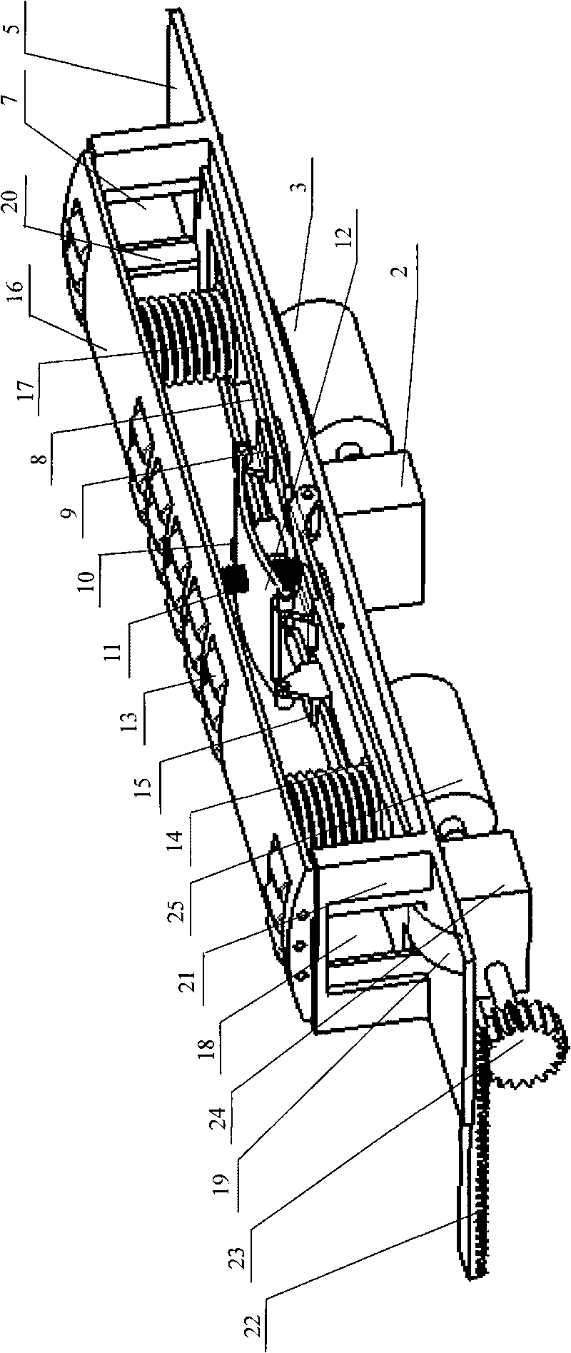
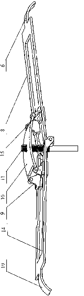
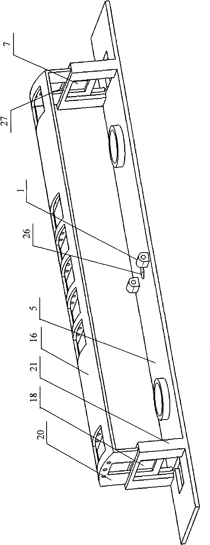
[0018] As shown in the figure, a lumbar support device for an electric driving seat includes a rear support plate 5 with a rising edge 21 and a front support plate 16 with a falling edge 20, and a chute is arranged in the rising edge 21 of the rear support plate 5 27, the falling edge 20 of the front support plate 16 is set in the chute 27 of the rising edge 21 of the rear support plate 5, the falling edge 20 of the front support plate 16 on the left side and the rising edge 21 of the rear support plate 5 A left through groove 18 is arranged on the top, and a right through groove 7 is arranged on the falling edge 20 of the front support plate 16 on the right side and the rising edge 21 of the rear support plate 5; Compression spring 17 and convexity adjustment transmission mechanism 12 are arranged, and described convexity adjustment transmission mechanism 12 comprises pressure plate 10, slide block 9, transmission screw rod 11 and left pull rod 14, right pull rod 8; The outer...


PUM


Abstract

The invention relates to a waist support device of an electric driver seat, which belongs to a fitting of an electric driver seat. The waist support device comprises a rear support plate with an ascending edge and a front support plate with a descending edge. The descending edge is arranged in a slide groove of the ascending edge. The descending edge and the ascending edge are provided with through grooves. A compression spring and a convexity adjusting driving mechanism are arranged between the front support plate and the rear support plate. A pull hook is arranged at the outer end of a pull rod of the convexity adjusting driving mechanism, and is arranged in the through groove. The inner end of the pull rod is hinged with a fixed hinge seat which is arranged on the rear support plate. The lower end of a driving screw rod is connected with the output end of a convexity adjusting gearbox through a through hole at the middle part of the rear support plate, and the input end of the convexity adjusting gearbox is connected with a convexity adjusting motor. A pressure plate with threads is arranged outside the driving screw rod. Both ends of the pressure plate are respectively provided with a slide block which is provided with a groove relative to the pull rod. A position adjusting motor is arranged at the outside of the rear support plate, and is connected with a gear through the gearbox. The gear is meshed with a gear rack.

Description

Technical field: [0001] The invention belongs to accessories of an electric driving seat, in particular to a lumbar support device for an electric driving seat. Background technique: [0002] At present, the convexity adjustment of the existing adjustable seat lumbar support device is realized by inflating and deflating the airbag, by tensioning and relaxing the spring steel wire (such as Chinese patent 200580043783.0), and by elastic plate It can be realized by elastic deformation (such as U.S. Patent No. 5,954,399-A), and it can also be realized by moving back and forth of the rigid body in the convex direction and so on. Since the driver's seat is inevitably subject to the impact pressure from the human body in front, elastic body supports such as airbags and spring steel wires have a buffering effect and make people feel more comfortable, but they are not convenient for the seat compared to rigid body supports. The internal space of the backrest skeleton moves back and ...

Claims


Application Information

Patent Timeline
Patent Type & Authority Applications(China)
IPC IPC(8): B60N2/66A47C7/46
Inventor 郭立新陈诲李金丽
Owner NORTHEASTERN UNIV
Why Eureka
Try Eureka