Axial loading device for electromagnetic rolling bearing

A technology of axial loading and rolling bearings, applied in the direction of mechanical bearing testing, etc., to achieve the effects of high automation, low manufacturing and use costs, and simple overall structure

Pending Publication Date: 2020-11-27
HENAN UNIV OF SCI & TECH
View PDF0 Cites 1 Cited by
  • Summary
  • Abstract
  • Description
  • Claims
  • Application Information

AI Technical Summary

Problems solved by technology

[0004] In order to solve the problem of continuous and accurate adjustment of the axial load within a certain range in the bearing test, the present invention provides an electromagnetic rolling bearing axial loading device, which is used to realize that when the outer ring of the test bearing is glued to the roller at high temperature during the bearing test, The axial loading device can be separated from the test bearing at the set time node, and an electromagnet is set in the clutch unit; a measurement and control unit is set to monitor the current signal of the motor and the temperature of the inner and outer rings and rollers of the test bearing, and then control the axial load. The time node when the loading device is separated from the test bearing. In order to realize the precise and continuous adjustment of the applied axial force within a large range, the axial loading device adopts the method of "linear actuator + lever + electromagnet" to apply Axial force; in order to avoid the axial force exerted on the test bearing due to the gravity of the bearing seat cover and the test bearing outer ring, a lever mechanism is set in the axial loading device; and for the vibration generated during the test to affect the axial force For the problem of precise quantitative loading of force, a variable damping unit is set

Method used


Image

  • Axial loading device for electromagnetic rolling bearing
  • Axial loading device for electromagnetic rolling bearing
  • Axial loading device for electromagnetic rolling bearing

Examples


Embodiment Construction

[0034]In order to make the purpose, technical solutions and advantages of the embodiments of the present invention clearer, the technical solutions in the embodiments of the present invention will be clearly and completely described below in conjunction with the accompanying drawings in the present invention. Obviously, the described embodiments are the Some embodiments of the invention are not all embodiments. Based on the embodiments of the present invention, all other embodiments obtained by those of ordinary skill in the art without creative efforts fall within the protection scope of the present invention.

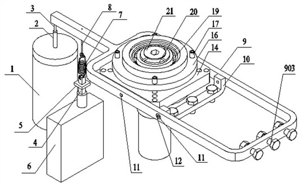
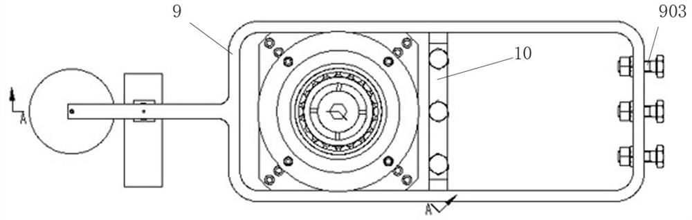
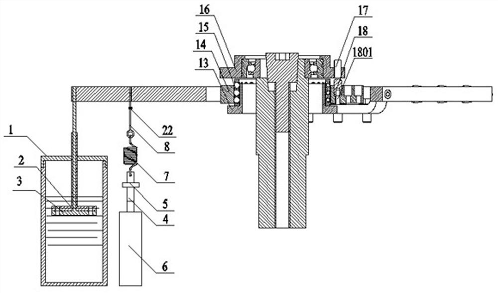
[0035] An electromagnetic rolling bearing axial loading device, such as Figure 1-Figure 3 As shown, including damping unit, loading unit, clutch unit, test bearing unit and measurement and control system;

[0036] Wherein, the damping unit comprises a bottom damping plate 3, a top damping plate 2 and a damping oil cylinder 1, the bottom damping plate 3 comprises a fi...


PUM


Abstract

The invention provides an axial loading device for an electromagnetic rolling bearing. The device comprises a damping unit, a loading unit, a clutch unit, a test bearing unit and a measurement and control system. According to the invention, the separation time node of the axial loading device and the test bearing can be controlled through the clutch unit, when a test bearing roller and an outer ring are glued at high temperature, rapid separation of the axial loading mechanism and the test bearing can be realized, a linear actuator + lever + electromagnet mode is adopted for loading, therefore, the purpose of accurately and continuously adjusting the axial force applied to the test bearing in a large range is achieved. Besides, the measurement and control system is adopted to monitor the magnitude of the applied axial loading force and the working state of the axial loading device and is used for controlling the working state of an electromagnetic clutch mechanism, the automation degree is high, the overall structure is simple and reasonable, and the manufacturing and using cost is low.

Description

technical field [0001] The invention belongs to the technical field of bearing test equipment, and in particular relates to an electromagnetic rolling bearing axial loading device. Background technique [0002] Rolling bearings are widely used in various types of mechanical equipment due to their remarkable advantages. Their motion accuracy determines the accuracy and performance of mechanical equipment, but rolling bearings are also one of the key components that are most likely to fail in mechanical equipment. There are many failure modes of bearings, among which the failure mode caused by slipping accounts for the highest proportion of the total failure; when sliding occurs during rolling bearing operation, not only the friction coefficient increases, but also a large amount of heat is generated, which will affect the motion accuracy and mechanical properties of rolling bearings. Efficiency, but also reduce the service life of rolling bearings. By applying proper axial p...

Claims


Application Information

Patent Timeline
Patent Type & Authority Applications(China)
IPC IPC(8): G01M13/04
CPCG01M13/04
Inventor 余永健司东宏李明岩于海晓
Owner HENAN UNIV OF SCI & TECH
Why Eureka
Try Eureka