Gear-shifting mechanism for manual transmission

A technology of manual transmission and gear shifting mechanism, which is applied in the direction of mechanical equipment, components with teeth, transmission device control, etc. It can solve the problems of driving comfort and shifting comfort, gear disengagement, and vehicle safety cannot be guaranteed, etc. question

Active Publication Date: 2010-06-30
CHONGQING TSINGSHAN IND
View PDF0 Cites 13 Cited by
  • Summary
  • Abstract
  • Description
  • Claims
  • Application Information

AI Technical Summary

Problems solved by technology

[0002] At present, the commonly used automotive manual transmissions, especially those used in passenger cars, are basically equipped with counterweights outside the gear shifting mechanism to reduce the gear shifting felt on the manual shift handle during the shifting process. The peak value of the force, and the counterweight and the shift arm are mostly rigidly connected together. There is a common problem in passenger cars equipped with this type of manual transmission, that is, the driving speed after the gear is engaged. During the process, the driver can clearly feel the vibration of the gear shift handle. If the mass of the counterweight is large, this vibration will be more obvious on the gear shift handle. The vibration of the regular shift lever seriously affects the driving comfort and gear shifting comfort. If the vibration is more serious, for example, when driving on bad road conditions, the vibration can even be large enough to cause the gear to be disengaged, causing the entire vehicle to lose weight. The safety cannot be guaranteed. If the counterweight is cancelled, the problem of poor shifting comfort caused by the shifting impact cannot be effectively solved. Therefore, the problem of shifting handle vibration is common in passenger cars with manual transmissions. With the continuous improvement of consumers' requirements for the comfort and safety of vehicle driving, it is imminent to solve the above problems

Method used


Image

  • Gear-shifting mechanism for manual transmission
  • Gear-shifting mechanism for manual transmission
  • Gear-shifting mechanism for manual transmission

Examples


Embodiment Construction

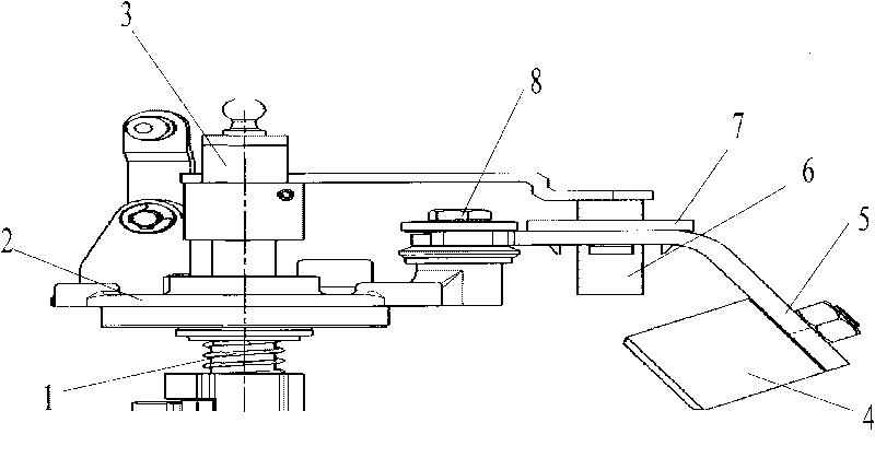
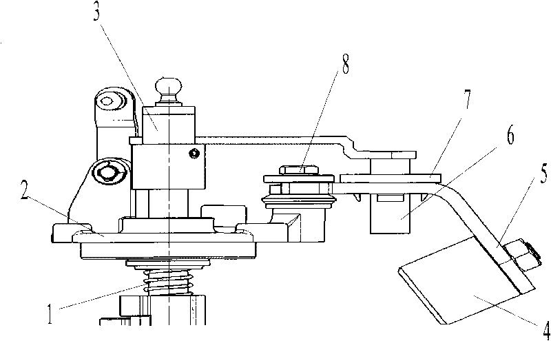
[0019] The invention provides a shift mechanism of a manual transmission, which can effectively block the transmission of the vibration of the balance weight to the shift handle.

[0020] The basic idea of ​​the present invention to solve the above-mentioned technical problems is: in the shifting mechanism of the automobile transmission, there is a counterweight connecting plate that can freely rotate around a shift shaft connected with the transmission casing, and the counterweight connecting plate It can be driven to rotate around the rotating strut bolt by the rotation of the counterweight toggle pin. The toggle pin of the counterweight is connected with the shift shaft of the shifting mechanism, and the counterweight is connected to the shift box through the bolts of the rotating pillar, and the bolts press the opening of the connecting plate of the counterweight to make the gears pressed by the bolts The counterweight and its connecting plate rotate freely around the rota...


PUM


Abstract

The invention embodiment discloses a gear-shifting mechanism for a manual transmission, which comprises a gear-shifting shaft, a gear-shifting box, a gear-shifting rotating arm, a weight block, a weight block connecting plate and a manual gear-shifting lever, wherein the gear-shifting shaft is arranged in the middle of the gear-shifting mechanism and assembled on the gear-shifting box capable of rotating freely and moving along the axial direction, the gear-shifting shaft is provided with the gear-shifting rotating arm which is connected together with the gear-shifting shaft, the gear-shifting rotating arm is connected with the manual gear-shifting lever in a moving state, a weight block shift pin is rigidly connected with the gear-shifting rotating arm and can drive the weight block connecting plate and the weight block to rotate around a rotating supporting bolt; and the weight block is rotationally connected on the rotating supporting bolt on the gear-shifting box through the weight block connecting plate. As the weight block is not directly connected with the gear-shifting rotating arm, and the gear-shifting shaft has no relation with the weight block except for the gear-shifting process, the vibration of the weight block is effectively prevented from transferring to a gear-shifting handle.

Description

technical field [0001] The invention relates to the technical field of automobile transmissions, and more specifically relates to a shift mechanism of a manual transmission. Background technique [0002] At present, the commonly used automotive manual transmissions, especially those used in passenger cars, are basically equipped with counterweights outside the gear shifting mechanism to reduce the gear shifting felt on the manual shift handle during the shifting process. The peak value of the force, and the counterweight and the shift arm are mostly rigidly connected together. There is a common problem in passenger cars equipped with this type of manual transmission, that is, the driving speed after the gear is engaged. During the process, the driver can clearly feel the vibration of the gear shift handle. If the mass of the counterweight is large, this vibration will be more obvious on the gear shift handle. The vibration of the regular shift lever seriously affects the dr...

Claims


Application Information

Patent Timeline
Patent Type & Authority Applications(China)
IPC IPC(8): F16H59/10
Inventor 龚为伦彭天河浦会力董其慧王文建
Owner CHONGQING TSINGSHAN IND
Why Eureka
Try Eureka