Luminous module

A technology of light-emitting modules and light-emitting diodes, which is applied in the direction of light sources, electric light sources, point light sources, etc., can solve the problems of high cost and unfavorable mass production, and achieve the effects of improving production efficiency, saving manufacturing costs, and saving assembly time

Active Publication Date: 2010-06-30
EVERLIGHT ELECTRONICS
View PDF0 Cites 7 Cited by
  • Summary
  • Abstract
  • Description
  • Claims
  • Application Information

AI Technical Summary

Problems solved by technology

[0003] Because the traditional light-emitting module needs to use the bulky plastic base 10 as a support, in addition, the flexible circuit board 20 must be fi

Method used


Image

  • Luminous module
  • Luminous module
  • Luminous module

Examples


Example Embodiment

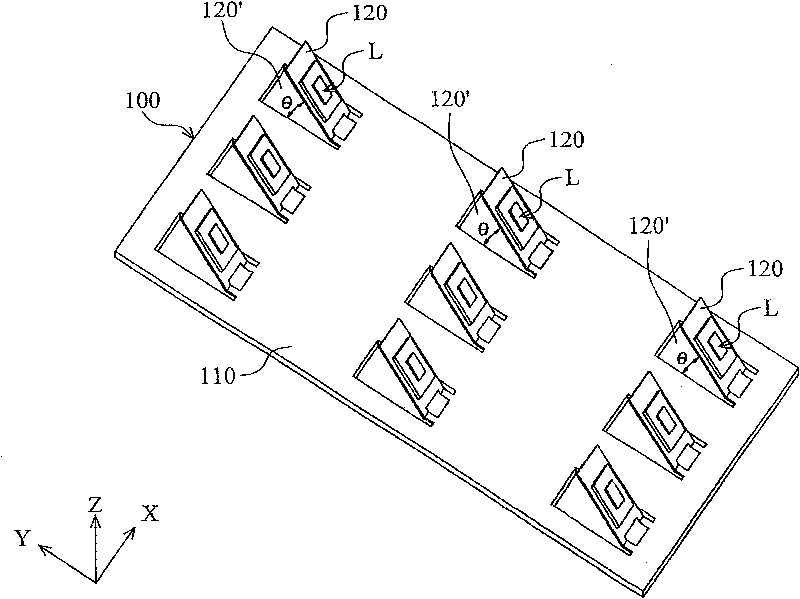
[0036] see figure 2 , the light emitting module of an embodiment of the present invention mainly includes a body 100 and a plurality of light emitting diodes L, the body 100 has an outer surface 110, a plurality of openings 120' and a plurality of bending structures 120, wherein the outer surfaces 110 are substantially parallel In the XY plane, the positions of the bending structures 120 correspond to the aforementioned openings 120 ′ respectively. It should be understood that the aforementioned bending structure 120 protrudes from the outer surface 110 toward the Z-axis direction, wherein an included angle θ is formed between the bending structure 120 and the outer surface 110 , and 0°<θ<180°.

[0037] like figure 2 As shown, the aforementioned light-emitting diodes L are respectively installed on the bending portion 120, wherein by forming an angle θ between the bending portion 120 and the outer surface 110, a light-emitting module with a three-dimensional shape can be fo...


PUM


Abstract

The invention relates to a luminous module. The luminous module comprises a base plate, a soft circuit board and a light-emitting diode, wherein the base plate is provided with a first surface, at least a first slot and at least a first bending part; the first bending part is connected with the first surface; the first slot is formed on the first surface so as to form the first bending part; the soft circuit board is combined with the base plate; the soft circuit board is provided with a second surface, at least a second slot and at least a second bending part; the second slot is formed on the second surface so as to form the second bending part; the second bending part is connected with the second surface and is combined with the first bending part; the first and second bending parts are protruded out of the second surface and form an included angle theta with the second surface; the angle theta is more than 0 degree and less than 180 degrees; and the light-emitting diode is arranged on the second bending part. The module of the invention needs no traditional plastic base and can be automatically produced and assembled so the production efficiency is greatly promoted and the assembling time and the manufacturing cost are saved.

Description

technical field [0001] The invention relates to a light-emitting module (light source module), in particular to a light-emitting module with a three-dimensional shape. Background technique [0002] First see figure 1 , the figure shows a light-emitting module with a three-dimensional shape, which is mainly composed of a plastic base 10 and a plurality of flexible circuit boards 20 . As shown in the figure, each flexible circuit board 20 is provided with a plurality of light emitting diodes L respectively. During assembly, the flexible circuit board 20 can be adhered to the corrugated surface 11 above the plastic base 10, so that the aforementioned various changes can be made. The light-emitting angle of the light-emitting diode L constitutes a three-dimensional lighting angle. [0003] Since the traditional light-emitting module needs to use the bulky plastic base 10 as a support, and the flexible circuit boards 20 must be fixed on the plastic base 10 one by one to complet...

Claims


Application Information

Patent Timeline
IPC IPC(8): F21S2/00F21V21/00F21V23/00F21V19/00H05K1/03F21Y101/02
Inventor 王仁晖
Owner EVERLIGHT ELECTRONICS
Why Eureka
Try Eureka